Abstract
Lighting designers must consider certain parameters in all retrofit lighting projects. They must also examine specific needs for specific (task) applications. Lighting systems should seek to maximize good lighting quality as well as energy efficiency.
INTRODUCTION
This article will provide overall general guidelines for the selection of appropriate lighting retrofit systems consistent with maximized lighting quality and energy efficiency. These recommended guidelines are not the only reasonable and practical solutions for each and every application situation, but they should serve as a process starting point to determine the most appropriate lighting system for a particular lighting application based on the task dynamics and minimized life-cycle cost. Recommendations in this article have been proven through years of successful application and performance. However, design details for your particular application should usually be determined with the help of an experienced lighting professional.
THE MAIN GOAL: QUALITY OF LIGHT
For any lighting retrofit application (interior or exterior), the main goal will be improved lighting quality that will enhance the client’s ability to use the lighting system properly. When lighting designs or retrofits are performed properly, energy and maintenance savings will be the advantageous by product, not the main goal. Simply turning out lights saves energy, but obviously, no one can function in the dark.
FACTORS TO BE CONSIDERED
Many factors are involved in selecting a method of reducing lighting energy. Each lighting application has its own intrinsic needs, and those must be considered prior to any change. Just removing lamps from fixtures, removing lamps while adding reflectors, rearranging fixture locations, or changing lamp wattages may reduce energy, but it may not be the most visually efficient way to make a change.
Glare
The most important consideration in lighting design is glare. Glare is the eye’s nemesis for seeing. Controlling glare and glare angles can be difficult if multiple functions are occurring at a single visual location or in different directions from a single location. Using efficient linear (fluorescent) sources generally lowers glare levels and allows the eye to function better.
Color Quality
The next important consideration should be the color quality of the scene. Our eyes work best when balanced color sources are used. The eyes contain rods and cones; cones are used for color sensing, and they sense basically in the red (long), green (medium), and blue (shorter) wavelengths. It then makes the most sense to use a source that has balanced color output in these same areas. Presently, the lamp Kelvin temperature that achieves this goal is the 4100 K lamp source, which is available in linear (fluorescent) or point sources (metal halide).
Uniform Light Levels
The third consideration is uniformity of light levels in the work area. This means that “hot” spots and dark spots are reduced to the greatest extent possible. The work area could be a desk, a parking lot, or anything in between. Each task will obviously be designed in a different manner, but the goals should be the same for any visual task.
Understanding the Human Eye
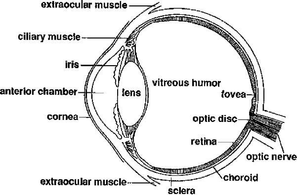
Lighting designers must understand how the human eye works before they can design an appropriate lighting system for a given situation. Understanding the human visual response system and applying this information to outdoor and commercial/industrial indoor designs will allow the designer to provide substantial energy saving opportunities, while also improving visual acuity (Fig. 1).
Fig. 1 Shows the architecture of the human eye.
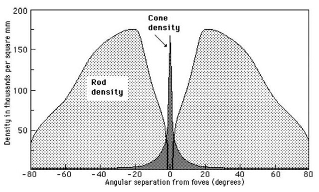
The central area, called the fovea, contains mainly cones. See Fig. 2.
Rods and cones are spread throughout the entire retinal area. Cones provide color sensing while rods provide acuity, or accuracy sensing. Rods and cones work together in most lighting situations. When both cones and rods are working, the eye is considered to be in mesopia. In extremely low light levels, mainly rods are functioning, and then the eye is considered to be in scotopia. In sunlight, or higher levels of artificial light (the upper level of mesopia has not been determined yet), the eye is said to be in photopia. The eye does not go directly from photopia to scotopia. Mesopia is the transitional area, and mesopic conditions can be experienced in parking lots at night or in many interior spaces during the daytime, including offices, warehouses, and factories.
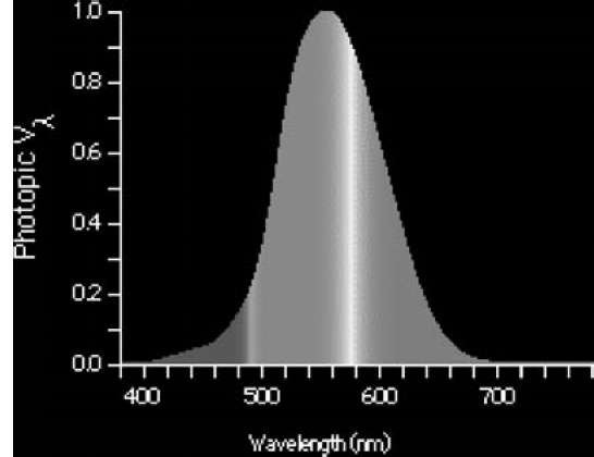
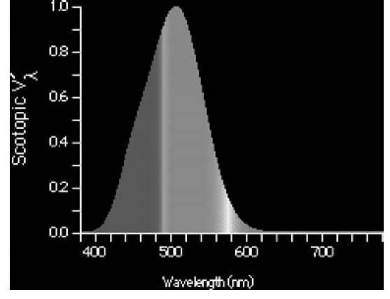
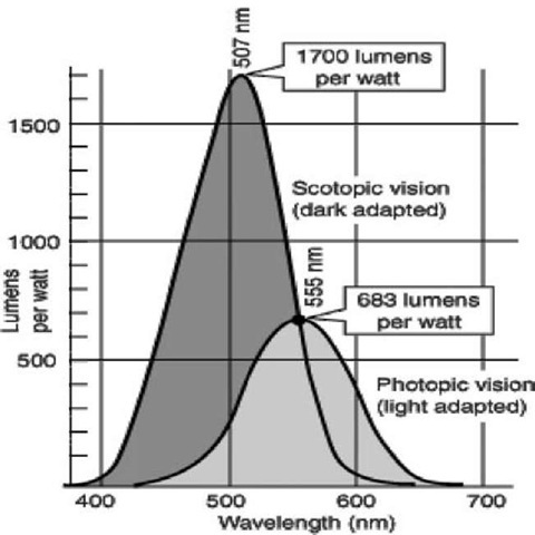
Figs. 3-5 show how the eye senses different frequencies and levels of light.
Fig. 5 shows the sensitivity ratio. Note how much more sensitive the eye is in the lower light levels to the bluer (whiter) frequencies. Most of today’s light meters do not sense this difference, while the human eye does.
(Graphics courtesy GSU Department of Astro Physics).
The scotopic efficacy curve was established in the same manner as the photopic curve. Its sensitivity is shifted, however, to peak at 507 nm, and it decreases in proportionally the same manner as the photopic curve. This results in the scotopic curve reaching a relative value of zero sooner in the visible spectrum than the daylight curve. As a consequence of this fact, our nighttime vision does not see red very well.
The scotopic efficacy curve is assigned a value of unity at 507 nm, and it is represented by the symbol V’ lambda. To determine spectral luminous efficacy, the scotopic efficacy value, V’ lambda, must be multiplied by 1700 lm (A lumen is the SI unit of luminous flux. Photometrically, it is the luminous flux emitted with a unit solid angle (1 sr) by a point source having a uniform luminous intensity of 1 cd.) per watt (W). This value was adjusted from 1754 to allow both curves to obtain the same value of 683 lm/W at 555 nm. So, a source we see with our dark-adapted vision at 507 nm produces 1700 lm for every watt radiated, and any other wavelength produces a fraction of that value based on the efficacy curve.
If we have a better balance of light colors, we do not need as many lumens (and therefore as many footcandles (A footcandle is a unit of illuminance equal to 1 lm/ft2 or 10.76 lux.) or lux (A lux is one lumen per square meter (1m/m2)).) to be able to function visually. If the scene uses dominantly blue light frequencies (mixed with red and green), our eyes can sense details more accurately. However, as mentioned above, glare can cause the reverse, or blinding effects, which make the eye less efficient. Many people dislike the newer (bluer than normal) automobile headlights. Why? Because the eye is more sensitive to blue light at night, and the glare these new lights create is discomforting and sometimes disabling. Standard headlight coloration with “brights-on” also causes discomfort or disabling conditions. Because most cars use the warmer color headlights, these new halogen (cooler color) headlamps stand out more due to their unique coloration. The same factors of color and glare involved in headlights for roadway lighting must be considered for any task, indoors or out.
Fig. 2 Retinal rod and cone density chart.
Fig. 3 Photopic (daytime) eye sensitivity curve (CIE). Note peak at 555 nm.
Fig. 4 Scotopic (starlight) CIE. Note peak at 507 nm and smaller amount of the last Section (red in original CIE) in spectrum.
Fig. 5 Scotopic/photopic vision sensitivity chart.
LIGHT WHERE YOU NEED IT, WHEN YOU NEED IT
There are other factors and systems to consider for conserving maximum amounts of energy, other than light sources and how they are used. The Illuminating Engineering Society of North America’s (IES/NA’s) motto for this millennium is “Light Where You Need It, When You Need It.”
Use of Motion Sensors
Motion sensors add dramatically to energy savings because most people do not turn the lights off when they leave an area. Although motion sensors seem like a good solution for controlling lighting, there are some cases where they are inappropriate. If High Intensity Discharge (HID) sources (high-pressure sodium (HPS), mercury vapor, or metal halide in any form) are used, motion sensors should not be installed due to the long re-strike/ warm-up times HIDs require. Motion sensors can be used successfully on fluorescent or incandescent sources. However, incandescent sources are rarely used in new commercial or industrial facilities. If we use motion sensors on fluorescent sources, including all Compact Fluorescent Lamps (CFLs), the number of times the lamp will cycle in a given day must be considered. Fluorescents should not be cycled (turned on/off) more than 12 times/day, or lamp life will suffer significantly. There are a variety of ballast types on the market today that will work properly with motion sensors to provide good longevity for the ballast and lamp. These are called “Program Start” or “Program Rapid Start” ballasts. These ballasts preheat the lamp anodes and cathodes to minimize thermal shock to the lamp filament, thereby increasing the lamp’s life substantially. Motion sensors should not be used with screw-in CFLs because their internal ballast is not suited for motion sensor use.
Substantial Lamp Life Increases
Fluorescent lamps using an instant-start ballast have a rating of 14,000 hours. If they use the newer program-start ballasts, they will now have a lamp life of over 24,000 h. These ballasts cost a little more, but are well worth the small extra costs. The newer fluorescent lamps, including twin T5 (PL, Biax, Dulux), linear T5/T5 HO, and T8 lamps, now maintain 90 + % in lumen output for 90% lamp life. No other sources maintain that much efficiency to date, including “induction” systems.
Induction Systems
A relatively new lighting system has been developed that uses electrodeless lamp sources with inherent long life results (50,000-100,000 h). The driver or ballast is basically the same type of device that operates a microwave oven to provide light output from the source. The driver/ballast cost is very high at this writing, and it is suggested that the driver be replaced when the source is replaced. These systems should only be considered for extremely difficult replacement applications. At least two manufacturers have sources/drivers product available, and many fixture manufacturers are now bringing products to market. Lumen depreciation should be carefully considered for these systems.
Linear T5 Lamped Systems
Caution must be used when selecting linear T5 lamped units that are enclosed and gasketed. Due to high temperature operation of the linear T5 (not twin T5) lamps, only thermally tested linear T5 fixture systems should be chosen. The small lampholder is the weakest link in the system, and can degrade prematurely. Cracks in the lampholder will affect lamp and ballast life. This can be alleviated or solved by selecting only twin T5 lamped systems, especially for enclosed fixture applications, such as all outdoor applications, and many indoor applications. The larger, more robust lampholder for the twin T5 lamp is better suited for enclosed and gasketed systems.
Lighting Systems for Dirty Areas
In dirty environments such as factories, warehouses, shop areas, etc. lensed and gasketed luminaires should be used to help maintain higher light levels longer. When luminaries are open, dirt gets onto the lamp and reflector and creates large system inefficiencies by reducing light output. It’s like a dirty carburetor on a car—the car still runs, but at reduced efficiency. Cleaning lamps and reflectors is much more expensive than cleaning a lensed and gasketed fixture. Because open luminaires cannot be cleaned while energized, the circuit must be turned off, affecting a large work area where no production can occur. Loss of production time can be very expensive. Lensed luminaires can be cleaned with soap/water (or other cleaning agents) on rolling scaffolding while they are energized, and the cleaning affects only a small area at a time. Production does not have to shut down, and cleaning the lens is much quicker than removing lamps to clean not only the lamps, but the reflectors. The labor savings can be very substantial.
Lensed luminaires keep lamps and reflectors clean longer and maintain higher light levels. The lighting project at Macy’s (Brooklyn) mentioned above used enclosed and gasketed luminaries in the shops area. The total savings in this dirty environment was 77% in lighting energy savings.
Dimming
Dimming is another somewhat useful tool, but it only saves a portion of the energy that motion sensors save, so it is important to understand why dimming would be better than no light at all. With some of the HID dimming systems, by the time the light is brought from dimmed to full output, the need for increased lighting no longer exists.
PUTTING IT ALL TOGETHER
Good glare control, proper source coloration, and good uniformity are required for a retrofit or a new design to be considered efficient. Once the system is designed, controlling the system’s usage can also save substantial energy. An energy management system (EMS) can be used to control lighting with photocells, switches, dimming, or motion sensing.
Each EMS must be programmed properly, and the entire system must be commissioned (checked to make sure it is functioning properly). For verification purposes, periodic reviews of the system operation should be performed, with the timing dependent upon the complexity of the system and the size of the facility. If an EMS is not used, then the proper operation of the components (photocells, motion sensors, switches, etc.) must be periodically verified.
DESIGN PARAMETERS
Each lighting application has a recommended range of lighting levels. In other words, there is no one specific light level that has to be used for any given application. The most recent IES Lighting Handbook/2000 provides a given level of recommended light levels (footcandles or lux) along with a chart or matrix of other factors that must be considered in varying degrees to complete an efficient, quality lighting system design for that application. The final overall design parameters should be determined by a lighting professional to ensure proper benefits and results.
Take parking lot lighting as an example. In various chapters of the IES Lighting Handbook/2000, different levels of light are recommended depending on the various committees’ positions. The Security Lighting Committee may call for a higher level of illumination when security is an issue. The parking lot subcommittee of the Roadway Lighting Committee may recommend a low level of light, especially for private parking lots vs public parking lots. The obtrusive light subcommittee may recommend yet a lower light level to minimize, reduce, and restrict light trespass and light pollution. This might lead to the use of controls to have the proper level of light at the time it is needed. Fifty lux (five footcandles) of light might be appropriate while a shopping center is open; but after it closes, these light levels could be reduced by 50% or the lights should all be turned off because no one is on the property. If motion detectors were used with instant-on fluorescent systems, a security alarm could also be connected to the system, and security/police would be notified when the motion sensor activated. High-resolution digital cameras could also be incorporated to record when the sensor activates, and the results could be used for prosecutorial purposes.
CALCULATIONS
Lighting design software is the best way to design a lighting system, but there are other fairly simple ways to estimate or budget for lighting. Methods include wattage per square foot and lumens per square foot. Most people are more familiar with wattages than lumens. We can’t see a lumen or a footcandle or a lux in our mind. We do know what a watt is, and that we have to pay for using them. However, both measures have positive and negative aspects.
Let’s tackle the negatives first. We have to understand the relationship between watts and lumens. You might think that the more lumens per watt a source possessed, the more light we would get. The best (or maybe worst) example is from a source called low-pressure sodium (LPS). The lamp catalogs say that this source can provide up to 180 lm/W. That sounds good, except for the fact that the eye only uses about 25% of those lumens to send images to our brain, which provide us visual information. If you are a security guard who wants to be able to identify clothing color, hair color, skin color, or the color of a vehicle, you can’t do it accurately with an LPS system because all colors appear to be shades of brown, orange, and purple. Therefore, LPS is not a very good source to use for our eye to send accurate images to our brain.
The next most frequently used source today is HPS. Our eyes can only use about 55%-62% of those 90-110 lm/W, but it makes today’s light meter read high.
What source is best for our eye? We have already discussed that whiter sources provide better information to our eye and thus more accurate information to our brain so that we can make decisions. This means we should consider metal halide (MH) and fluorescent (FL) sources, whose Color Rendering Index (The CRI is a measure of the degree of color shift objects undergo when illuminated by the light source as compared with those same objects when illuminated by a reference source of comparable color temperature.) (CRI) is much higher than LPS or HPS. Fluorescents lamps have from 60 to 93 CRI, while metal halides are improving, but today still have 50-90 CRIs.
We also discussed that glare needs to be considered in good lighting design. Most of the time, the less glare there is, the better. Point sources (HPS, MH) produce more glare, and should only be considered when FL cannot possible be used. How do we calculate glare? There is no metric today that provides an accurate indication of glare. The Visual Comfort Probability (VCP) doesn’t work well for interior applications, and is in the process of revision. The European effort, called Unified Glare Ratio (UGR), which is also under revision, is supposed to work for interior as well as exterior applications. Diffusers, diffractors, and lenses can help reduce glare, but then luminaire efficiency suffers, which reduces system efficiency as well, and energy and operating costs shoot upward.
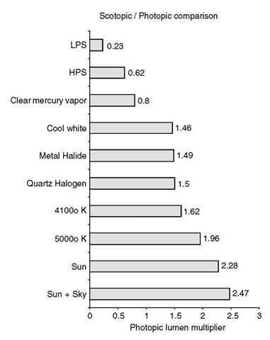
A new method that compensates for visual efficacy using a multiplier called the Scotopic/Photopic (S/P) ratio is gaining acceptance today. It uses a correction factor to provide a more accurate assessment of what our eye actually senses. A new meter is now finally available (2005) that uses the S/P ratio correction factor and an algorhythm to indicate a visual effectiveness output. The new meter is a radiometer and a photometer combined. The radiometer measures the intensity of each wavelength in the scene (not just the source lamp) and calculates via the S/P ratio the combined amounts of all the energy, then applies that result to the photometer to provide a visual effectiveness measurement. See the chart below for basic multiplying factors for various lamp sources. The visual effectiveness readout can be two to three times higher than just the photopic method of light measurement (today’s method of measuring). This means we have been and are wasting from 33 to 66% of our lighting energy costs using today’s light meters! This is something we can no longer afford to do. The CIE (Commission Internationale de l’Eclairage), who creates lighting standards, should have developed a New Method Of Measurement For Mesopic Illumination in mid—to late 2006. This method of design can actually save the most energy.
Chart numbers provided by Dr. Sam Berman, Ph.D., FIES.
Emergency Lighting
Emergency lighting must be considered for most applications today, and it is required by many local building codes. When the main lighting system is an HID system, an emergency back up system is required—even for many exterior applications. These systems can be battery/inverter systems, running inverters, backup generators, or even solar-powered back up systems, etc. If the main lighting system is a fluorescent lighting system, backup emergency ballasts can be built into the fixtures.
Usually some of the luminaires use emergency ballasts that reduce the light output for a given amount of time. Emergency generators can run larger loads than inverter systems, but normally cost more initially, as well as to maintain. Using the most efficient fluorescent lighting fixtures will reduce generator loads and, therefore, initial costs. One military base changed their main gate entrance lighting system from metal halide lamps (1000 W each) to high-quality, outdoor, weatherproof fluorescent lamps (212 W each), and saved over 40,000 W of generator need. This savings almost paid for the entire lighting system changeover. The author of this article can provide further information about this and other major energy-conserving case studies.
CONCLUSION
To retain the most energy and have the most visually efficient lighting system possible, select the proper lamp source, use the most appropriate luminaire, position it properly for the specific application, and control it with the best device for the specific application. This properly designed system should provide the optimum visual effectiveness level. If handled correctly, a quality designed lighting system will provide tangible and even intangible returns (such as higher productivity) for its owners/users. Proper lighting levels will now be calculated more accurately and it will be easier to provide higher-quality lighting systems, lower maintenance costs, and better value for owners and users. Emergency lighting design can be extremely important for each individual application, and the best methods must be determined for cost and effectiveness.
