Introduction
The production of ferro- and ferrimagnetic materials is a large-scale operation, measured in quantity as well as in currency. (This is in contrast to the products of the computer industry, where the price of the material that goes into a chip is a minute fraction of the device fabrication cost.) As an example, the annual sales of so-called electrical steel, used for electromotors and similar devices, reach the millions of tons and their market values are in the hundreds of millions of dollars. Other large-scale production items are permanent magnets for loudspeakers, etc., and magnetic recording materials. The following sections will give some impression about the technology (i.e., mostly materials science) which has been developed to improve the properties of magnetic materials.
Electrical Steels (Soft Magnetic Materials)
Electrical steel is used to multiply the magnetic flux in the cores of electromagnetic coils. These materials are therefore widely incorporated in many electrical machines in daily use. Among their applications are cores of transformers, electromotors, generators, or electromagnets.
In order to make these devices most energy efficient and economical, one needs to find magnetic materials which have the highest possible permeability (at the lowest possible price). Furthermore, magnetic core materials should be capable of being easily magnetized or demagnetized. In other words, the area within the hysteresis loop (or the coercive force, Hc) should be as small as possible (Fig. 15.6). We remember that materials whose hysteresis loops are narrow are called soft magnetic materials.
Electrical steels are classified by some of their properties, for example, by the amount of their core losses, by their composition, by their permeability, and whether or not they are grain-oriented. We shall discuss these different properties in detail.
The energy losses which are encountered in electromotors (efficiency between 50% and 90%) or transformers (efficiency 95-99.5%) are estimated to be, in the United States, as high as 3 x 10¹⁰ kWh per year, which is equivalent to the energy consumption by about 3 million households, and which wastes about $2 x 10⁹ per year. If by means of improved design of the magnetic cores, the energy losses would be reduced by only 5%, one could save about $108 per year and several electric power stations. Thus, there is a clear incentive for improving the properties of magnetic materials.
Core Losses
The core loss is the energy that is dissipated in the form of heat within the core of electromagnetic devices when the core is subjected to an alternating magnetic field. Several types of losses are known, among which the eddy current loss and the hysteresis loss contribute the most. Typical core losses are between 0.3 and 3 watts per kilogram of core material (Table 17.1).
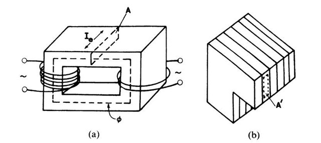
Let us first discuss the eddy current. Consider a transformer whose primary and secondary coils are wound around the legs of a rectangular iron yoke (Fig. 17.1(a)). An alternating electric current in the primary coil causes an alternating magnetic flux in the core, which, in turn, induces in the secondary coil an alternating electromotive force, Ve, proportional to df/dt, see (14.7) and (15.9),
Concurrently, an alternating emf is induced within the core itself, as shown in Fig. 17.1(a). This emf gives rise to the eddy current, Ie. The eddy current is larger, the larger the permeability, m (because B = m0m ‘ H), the larger the conductivity, s, of the core material, the higher the applied frequency, and the larger the cross-sectional area, A, of the core. (A is perpendicular to the magnetic flux, f, see Fig. 17.1(a).) We note in passing that, particularly at high frequencies, the eddy current shields the interior of the core from the magnetic field, so that only a thin exterior layer of the core contributes to the flux multiplication (skin effect).
In order to decrease the eddy current, several remedies are possible. First, the core can be made of an insulator in order to decrease s. Ferrites are thus effective but also expensive materials to build magnetic cores (see Section 15.1.5).
Table 17.1. Properties of Some Soft Magnetic Materials.
aAbove Bs the magnetization is constant ani![]() is unity.
is unity.
Figure 17.1. (a) Solid transformer core with eddy current, Ie, in a cross-sectional area A. Note the magnetic flux lines f. (b) Cross section of a laminated transformer core. The area A’ is smaller than area A in (a).
They are indeed used for high-frequency applications. Second, the core can be manufactured from pressed iron powder whereby each particle (which is about 50-100 mm in diameter) is covered by an insulating coating. However, the decrease in s, in this case, is at the expense of a large decrease in m. Third, the most widely applied method to reduce eddy currents is the utilization of cores made out of thin sheets which are electrically insulated from each other (Fig. 17.1(b)). This way, the cross-sectional area, A, is reduced, which in turn decreases Ve (17.1), and additionally reduces losses due to the skin effect. Despite the lamination, a residual eddy current loss still exists, which is caused by current losses within the individual laminations and interlaminar losses that may arise if laminations are not sufficiently insulated from each other. These losses are, however, less than 1% of the total energy transferred.
Hysteresis losses are encountered when the magnetic core is subjected to a complete hysteresis cycle (Fig. 15.6). The work thus dissipated into heat is proportional to the area enclosed by a B/H loop. Proper materials selection and rolling of the materials with subsequent heat treatment greatly reduces the area of a hysteresis loop (see below).
Grain Orientation
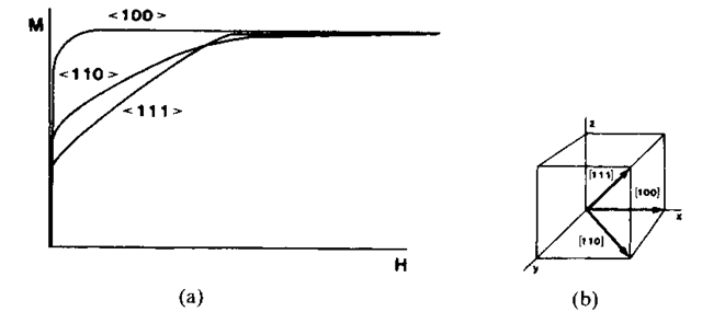
The permeability of electrical steel can be substantially increased and the hysteresis losses can be decreased by making use of favorable grain orientations in the material. This needs some explanation. The magnetic properties of crystalline ferromagnetic materials depend on the crystallographic direction in which an external field is applied, an effect which is called magnetic anisotropy. Let us use iron as an example. Figure 17.2(a) shows magnetization curves of single crystals for three crystallographic directions.
Figure 17.2. (a) Schematic magnetization curves for rod-shaped iron single crystals having different orientations (virgin curves). The magnetic field was applied in three different crystallographic directions. (Compare with Fig. 15.6, which refers to polycrystalline material). (b) Reminder of the indices which identify directions in space. (See also Footnote 14 in Section 5.6).
We observe that if the external field is applied in the (100) direction, saturation is achieved with the smallest possible field strength. The (100) direction is thus called the "easy direction." (In nickel, on the other hand, the (111) direction is the easy direction and (100) is the hard direction.)
This experimental finding gives us, incidentally, some clues about the spontaneous orientation of the spin magnetic moments in the demagnetized state. They are aligned in the easy direction. As an example, in virgin iron the spins are aligned along the (100) directions. Now, suppose that an external field is applied parallel to an easy direction. Then, the domains already having favorable alignment grow without effort at the expense of other domains until eventually the crystal contains one single domain (Fig. 15.9). The energy consumed during this process (which is proportional to the area between the magnetization curve and the horizontal line through Ms) is used to move the domain walls through the crystal.
A second piece of information needs to be considered, too. Metal sheets, which have been manufactured by rolling and heating, often possess a "texture", i.e., they have a preferred orientation of the grains. It just happens that in a-iron and a-iron alloys the (100) direction is parallel to the rolling direction. This property is exploited when utilizing electrical steel.
Grain-oriented electrical steel is produced by initially hot-rolling the alloy followed by two stages of cold reduction with intervening anneals. During the rolling, the grains are elongated and their orientation is altered. Finally, the sheets are recrystallized, whereby some crystals grow in size at the expense of others (occupying the entire sheet thickness).
In summary, the magnetic properties of grain-oriented steels are best in the direction parallel to the direction of rolling. Electrical machines having core material of grain-oriented steel need less iron and are therefore smaller; the price increase due to the more elaborate fabrication procedure is often compensated by the savings in material. For details, see Table 17.1.
Composition of Core Materials
The least expensive core material is commercial low carbon steel (0.05% C). It possesses a relatively small permeability and has about ten times higher core losses than grain-oriented silicon iron (Table 17.1). Low carbon steel is used where low cost is more important than the efficient operation of a device. Purification of iron increases the permeability but also increases conductivity (eddy current!) and price.
Iron-silicon alloys containing between 1.4 and 3.5% Si and very little carbon have a higher permeability and a lower conductivity than low carbon steel (see Table 17.1). Furthermore, because of special features in the phase diagram ("y-loop"), heat treatments of these alloys can be performed at much higher temperatures without interference from phase changes during cooling. The core losses decrease with increasing silicon content. However, for silicon concentrations above 4 or 5 weight %, the material becomes too brittle to allow rolling. Grain orientation in iron-silicon alloys (see above) further increases the permeability and decreases the hysteresis losses. Other constituents in iron-silicon alloys are aluminum and manganese in amounts less than 1%. They are added mainly for metallurgical reasons, because of their favorable influence on the grain structure and their tendency to reduce hysteresis losses. Grain-oriented silicon "steel" is the favored commercial product for highly efficient-high flux multiplying core applications.
The highest permeability is achieved for certain multicomponent nickel-based alloys such as Permalloy, Supermalloy, or Mumetal (Table 17.1). The latter can be rolled into thin sheets and is used to shield electronic equipment from stray magnetic fields.
Amorphous Ferromagnets
The electrical properties of amorphous metals (metallic glasses) and their methods of production have already been discussed in Section 9.4. In the present context, we are interested only in their magnetic properties, in particular, as flux multipliers in transformers, motors, etc. Some amorphous metals (consisting of iron, nickel, or cobalt with boron, silicon, or phosphorus) have, when properly annealed below the crystallization temperature (for strain relaxation), a considerably higher permeability and a lower coercivity than the commonly used grain-oriented silicon-iron, see Table 17.1. Further, the electrical resistivity of amorphous alloys is generally larger than their crystalline counterparts, which results in smaller eddy current losses.
However, amorphous ferromagnets possess a somewhat lower saturation induction (Table 17.1) (which sharply decreases even further at elevated temperatures) and their core losses increase rapidly at higher flux densities (e.g., above 1.4 T). Thus, the application of metallic glasses for flux multiplication purposes is, at the present, limited to devices with small flux densities, i.e., low currents, such as for transformers (e.g., for communication equipment), magnetic sensors, or magnetostrictive transducers.
Permanent Magnets (Hard Magnetic Materials)
Permanent magnets are devices that retain their magnetic field indefinitely. They are characterized by a large remanence Br (or Mr), a relatively large coercivity Hc, and a large area within the hysteresis loop. They are called hard magnetic materials (see Section 15.1.3).
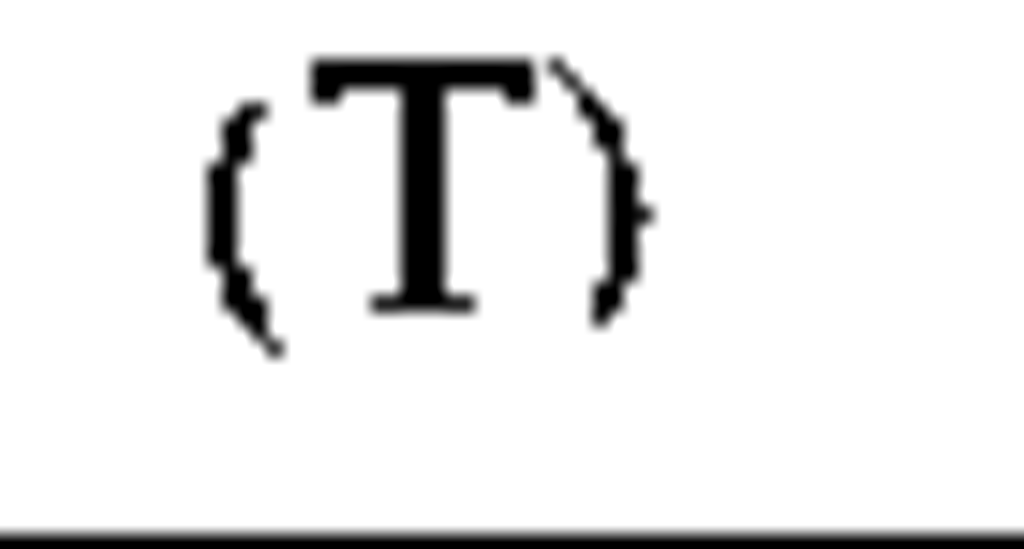
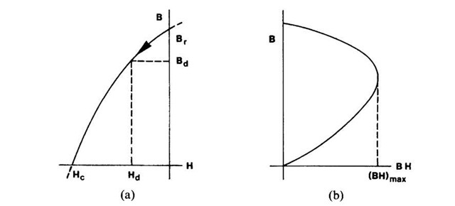
The best means to visualize the properties of permanent magnets is to inspect their demagnetization curve (Fig. 17.3), which is a part of a hysteresis loop, as shown in Fig. 15.6. Another parameter which is used to characterize hard magnetic materials is the maximum energy product, (BH)max, which is related to the area within the hysteresis loop. We see immediately from Fig. 17.3 that B times H is zero at the intercepts of the demagnetization curve with the coordinate axes, and that the energy product peaks somewhere between these extreme values, depending on the shape and size of the hysteresis curve. The values of Br, Hc, and (BH)max for some materials which are used as permanent magnets are listed in Table 17.2.
The remanence, Br, shown in Fig. 17.3 or listed in Table 17.2 is the maximal residual induction which can be obtained in a circular, close-loop magnet inserted in a coil. However, all permanent magnets need to have exposed poles in order to be useful.
Figure 17.3. (a) Demagnetization curve for a ferromagnetic material. (Second quadrant in a B-H diagram.) (b) Energy product, BH, as a function of induction, B.
Table 17.2. Properties of Materials Used for Permanent Magnets.
The necessary air gap between the north and south poles reduces the remanence, because the exposed poles create a demagnetizing field, Hd, which acts in the opposite direction to the B lines. We understand intuitively that the demagnetizing field depends on the shape, size, and gap length of a magnet. Thus, a reduced value for the residual induction, termed Bd, is obtained as shown in Fig. 17.3. Another effect which reduces the useful magnetic field is fringing near the air gap and leakage from the sides of a magnet (Fig. 17.4).
We now turn to the properties of some common hard magnetic materials. Today, many permanent magnets are made of Alnico alloys, which contain various amounts of aluminum, nickel, cobalt, and iron, along with some minor constituents such as copper and titanium (Table 17.2). Their properties are improved by heat treatments (homogenization at 1250°C, fast cooling, and tempering at 600°C, Alnico 2). Further improvement is accomplished by cooling the alloys in a magnetic field (Alnico 5). The best properties are achieved when the grains are made to have a preferred orientation. This is obtained by cooling the bottom of the crucible after melting, thus forming long columnar grains with a preferred (100) axis in the direction of heat flow. A magnetic field parallel to the (100) axis yields Alnico 5-DG (directional grain).
The superior properties of heat-treated Alnico stem from the fact that during cooling and tempering of these alloys, rod-shaped iron and cobal-trich a-precipitates are formed which are parallel to the (100) directions (shape anisotropy). These strongly magnetic precipitates are single-domain particles and are imbedded in a weakly magnetic nickel and aluminum matrix (a). Alnico alloys possess, just as iron, a (100) easy direction (see Fig. 17.2) and have also a cubic crystal structure. Alnico alloys are mechanically hard and brittle and can, therefore, only be shaped by casting or by pressing and sintering of metal powders.
Figure 17.4. Fringing and leakage of a permanent magnet.
The newest hard magnetic materials are made of neodymium-boron-iron, see Table 17.2. They possess a superior coercivity and thus a larger (BH)max. The disadvantage is a relatively low Curie temperature of about 300° C.
They crystallize in the form of plates with the hexagonal c-axis (which is the easy axis) perpendicular to the plates. Some preferred orientation is observed, because the flat plates arrange parallel to each other during pressing and sintering. Ferrite powder is often imbedded in plastic materials, which yields flexible magnets. They are used, for example, in the gaskets of refrigerator doors.
High carbon steel magnets with or without cobalt, tungsten, or chromium are only of historic interest. Their properties are inferior to other magnets. It is believed that the permanent magnetization of quenched steel stems from the martensite-induced internal stress, which impedes the domain walls from moving through the crystal.


