5.2
5.2.1
Variable-Reluctance Step Motors
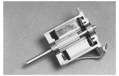
The construction of variable-reluctance (VR) motors is generally as shown in Fig. 5.45. There is a stator assembly consisting of an insulated lamination stack with copper coils wound around the teeth. The stator assembly is positioned within a housing or main frame such that its location is secured. The rotor assembly consists of a steel magnetic core, a steel output shaft, and bearings. The rotor assembly is centrally located inside the stator assembly by end frames or bearing supports.

FIGURE 5.45 Cutaway view of a variable-reluctance step motor.
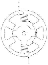
Motor Operation. When a stator phase is energized, the soft-iron rotor is electro-magnetically attracted to the stator poles (Fig. 5.46). A rotor tooth attempts to line up with the nearest energized stator pole. A magnetic flux path exists from stator pole to rotor tooth, through the rotor to a different rotor tooth and stator pole, and around the stator back iron. When the rotor teeth are directly lined up with the sta-tor poles, the rotor is in a position of minimum reluctance to the magnetic flux. If an external torque is applied to the rotor, a counteracting torque is developed which tends to restore the rotor to a position of minimum reluctance. A rotor “step” takes place when one stator phase is deenergized and the next phase in sequence is energized, thus creating a new position of minimum reluctance for the rotor.
Variable-reluctance step motors are capable of high stepping rates because of their high torque-to-rotor inertia ratio. The many possible combinations of rotor and stator teeth and phases lead to the availability of a wide range of step angles.

FIGURE 5.46 Wiring diagram for one phase of a variable-reluctance step motor.
