5.1.2
Mechanical Parameters. All designs must start with some parameters and assumptions. Generally, there is a specification of some type which includes output performance, available power input, mechanical mounting method, and means of connecting the load. First, look at the intended application and determine whether an inner- or outer-rotor motor would be the first choice. Some common indicators are charted in Table 5.2.
Establishing Motor Cross-Section Dimensions. It should be noted here that magnetic-circuit design is an interactive process and that the following rules are just guidelines to establish a starting point. At this point, the outside diameter of the motor and the shaft diameter have been selected. The next task is to roughly proportion the magnetic-circuit components to establish a starting point for the design. First look at the outer-rotor motor (Fig. 5.21). Then look at the inner-rotor motor
(Fig. 5.22).
The shaft and bearing space has already been established, so the space for active material that remains is the area between the shaft hole and the outside diameter. Next, decide on the air gap. Gaps on the order of 0.020 to 0.040 in per side are very common. The smaller the air gap, the more flux that is available, but the higher the value of cogging torque. Manufacturing tolerances on stack diameter and magnet thickness generally dictate a gap somewhere in the range stated. Start with the smallest gap your factory can comfortably hold. If in doubt, try 0.030 in to start.
In order to set the rotor and stator magnetic circuit dimensions, you must make some assumptions with respect to the level at which you will work the materials. This is accomplished by setting the flux densities in the magnetic circuit as outlined in
Table 5.3.
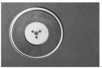
FIGURE 5.19 Axial air gap rotor with magnets.
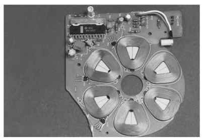
FIGURE 5.20 Axial air gap stator with windings.
TABLE 5.1 Comparison of Outer-Rotor and Inner-Rotor Motors
| Outer rotor | Inner rotor |
| Single phase or multiphase. | Single phase or multiphase. |
| Can be wound with dc armature-winding | Requires ac stator-winding |
| equipment. | equipment (more expensive). |
| Bifilar windings can be employed on single- | Salient-pole machines utilize more copper. |
| phase motors;50% copper utilization. | |
| Available copper space on distributed- | Distributed-winding motors provide |
| winding motors is less than on inner-rotor | smoother performance and better copper |
| types. | utilization. |
| Shorter end turns yield lower inductance | Longer end turns yield higher inductance and |
| and less copper loss. | more copper loss. |
| Greater rotor inertia. | Lower rotor inertia. |
| Less torque perturbation. | More torque perturbation. |
| Slower acceleration. | Fast acceleration. |
| Lower-energy magnets can be used. | Higher-energy magnets required. |
Rotor Back Iron. In the outer-rotor motor, this is usually a steel cup of some kind. To determine its thickness, keep in mind that the flux has a long steel path that requires mmf to overcome. Set the flux density equal to 75 kline/in2. Then:
![]()
But you don’t yet know how much flux will be needed. You do know, however, that it will be constant on a per-pole basis. This allows you to proportion the steel housing and lamination sections based on the relative flux densities given in Table 5.3. Taking the nominal values and setting the stator teeth as 1.0, you can define ratios for the remaining parts. There are still some problems to overcome before you can proceed. You have not yet decided on the number of poles or teeth.
Poles and Teeth. Some general rules on selecting the number of poles, teeth, and phases are presented in Table 5.4.
TABLE 5.2 Inner-Rotor Versus Outer-Rotor Motor Applications
| Requirement | Inner rotor | Outer rotor |
| Rapid acceleration | Very good | Poor |
| Heat dissipation | Very good | Poor |
| Low cogging | Okay | Good |
| Pump application | Okay | Good |
| Disk-drive application | Poor | Very good |
| Fan application | Poor | Very good |
| High side load | Good | Poor |
| Use with speed reducers | Good | Poor to okay |
| Reversible | Very good | Poor |
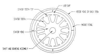
FIGURE 5.21 Outer-rotor motor
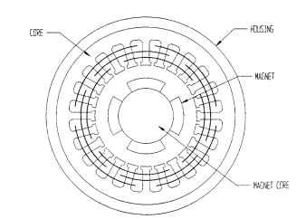
FIGURE 5.22 Inner-rotor motor
Number of Phases. Single-phase motors have poor conductor utilization, high torque ripple, and null zones that may create starting problems, but they are easy to wind and low cost and require only one or two power switches.
Two-phase motors also have poor conductor utilization, but the null zones are eliminated, the torque ripple is greatly reduced, and the cost is higher because a minimum of four power switches are required.
Three-phase motors have better conductor utilization, no starting problems, and greatly reduced torque ripple; they can get by with as few as three power switches, but they generally cost more to wind.
Increasing the number of phases to four or greater realizes small gains in copper utilization and torque ripple, but the costs of winding and power switches usually outweigh the gains.
TABLE 5.3 Preferred Flux Densities
| Flux density | ||
| Magnetic path section | kline/in2 | T |
| Rotor back iron | 70-80 | 1.09-1.24 |
| Stator tooth tips | 50-70 | 0.78-1.09 |
| Stator teeth | 110-125 | 1.71-1.94 |
| Stator yoke section | 80-100 | 1.24-1.55 |
As a starting point then, assuming that performance is as important as cost, the three-phase motor is a good choice.
Number of Poles. Some general rules of thumb to consider when selecting the number of poles are the following:
1. As the total number of poles increases, the requirement for rotor and stator back iron decreases because the total flux is spread over more poles reducing the density.
2. Since less back iron is needed, more space is available for windings, allowing for a reduction in copper losses.
3. More poles have more parts and cost more money.
Two-pole motors require substantial back iron and long winding spans, which means more expensive winding equipment. Four-pole motors require about half the back iron and have shorter coil spans. Although the equipment required may be the same as for two-pole motors, four-pole motors have shorter end turns—therefore less mutual inductance, less copper loss, and an easier time in winding.
TABLE 5.4 Effects of Changing Number of Poles, Teeth, and Phases
| Effect on design factors | |||||
| Change | Cogging | Speed | Torque | Active material utilization | Cost |
| Number of poles Increased Decreased |
Decreases Increases | Decreases Increases | Increases Decreases | Increases Decreases | Increases Decreases |
| Number of teeth Increased Decreased |
Decreases Increases | No change No change | No change No change | Increases Decreases | Increases Decreases |
| Number of phases Increased Decreased |
Decreases Increases | No change No change | No change No change | Increases Decreases | Increases Decreases |
Six-pole and higher motors allow for some additional gains in copper utilization and reduced back iron, but manufacturing costs and control-circuit costs start increasing disproportionately. So, barring a requirement for high torque, low speed or low cogging, a four-pole motor is also a good place to start.
Number of Teeth. So far, you have picked three phases and four poles. The next major item is the number of teeth. There are many combinations of teeth and poles that will work for motors having two, three, four and more phases. Common numbers of teeth for two-phase motors are 8, 12, 16, 24, and 48. Common three-phase numbers are 6, 9,12,15, 24, 36, and 48. There are obviously other numbers of teeth that will work for these motors. These are just some of the common ones. As the number of teeth selected increases, the number of slots available for winding also increases, resulting in more coils per pole. In general, one should choose the lowest number of teeth possible that will provide a reasonable winding pattern.
Some things to keep in mind as combinations of teeth, poles, and phases are chosen are the following:
^ Cogging. A torque perturbation occurs every time a magnet pole tip passes a stator tooth. Even numbers of teeth and poles cause a greater perturbation than uneven numbers because at any given time there are more pole tips passing teeth. This can be addressed by using an uneven number of teeth versus poles, which gives fewer poles passing teeth at a given time, or by skewing the stator or the magnets.
^ Manufacturability. Increasing the number of teeth to improve performance has its limits. As the number of teeth increases, the laminations may become difficult to punch, or the teeth may bend easily as the slots are wound.
For this example, choose 12 teeth. Therefore, you have chosen 3 phases, 4 poles
and 12 teeth.
To estimate the size of the respective components, look at the motor section in Fig. 5.23 and note the flux paths.
The flux from any one pole of this four-pole motor travels through the teeth to the stator yoke, then splits through the yoke, goes back through the teeth under the
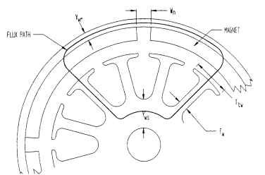
FIGURE 5.23 Outer-rotor motor flux path.
adjacent magnet pole across the air gap, goes through the magnet, splits through the rotor yoke, and goes back to the originating magnet. The magnet sets up the flux; all the flux goes across the gap (except for leakage), into the tooth tips, and through the teeth. When proportioning the sizes, refer to Table 5.5.
TABLE 5.5 Nominal Flux Densities
| Magnetic-circuit component | Nominal flux density, kline/in2 | |
| Outer rotor | Inner rotor | |
| Stator teeth | 115 | 115 |
| Stator tooth tips | 60 | 60 |
| Stator yoke | 90 | 75 |
| Rotor yoke | 75 | 90 |
Note that the stator and rotor yoke densities are inverted for the inner- and outer-rotor motors. This is because the short path can afford a higher density without resulting in too much mmf drop.
Since the flux density is inversely proportional to the area (B = <|)/A), and the area is proportioned to the width of the magnetic-circuit component times the length of the stack Lstk, the widths may be ratioed directly according to the flux density in
Table 5.5.
Ratio all components to the teeth as follows:
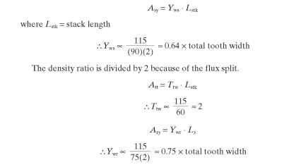
In the case of the outer-rotor motor, the length of the shell Ls is usually longer then the stator stack, so Ywr is more in the range of 30 to 40 percent of total tooth width.
To estimate the width of the teeth, assume that the area available after subtracting magnet area, air gap area, and stator yoke is to be divided up so that the slot area is approximately 2.5 times the tooth area. In this case, tooth area is the tooth width times its length in the radial direction. Assume straight teeth with parallel sides. Then take the total tooth width and divide it by the number of teeth per pole you have chosen. In this case, the number is 3. These dimensions may need to be modified to balance mmf drops once the magnetic circuit is solved.
Tooth-Tip Shapes. At this point, there are some things that need to be considered about the shape of the tooth tips. The outer-rotor motor (Fig. 5.21) has a stator that is much like a brush-type dc-motor armature, and they can be wound with similar equipment.The tooth-tip thickness Ttt (Fig. 5.24) should be large enough to keep the region from saturating as the magnet pole tips pass the edge of the tooth tip. This will reduce the torque perturbations and audible noise. A radius should be added at position 1 to allow for easy entry of the magnet wire and at position 2 to reduce magnetic saturation of this region.The width of the slot opening Wso should be wide enough to allow the largest-diameter wire you intend to use to be easily wound in place. It
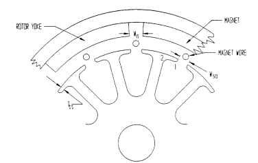
FIGURE 5.24 Outer-rotor tooth shapes.
should be kept small enough so that the magnet wire will be easily retained after the winding operation is complete.
The inner-rotor motor (Fig. 5.25) follows the same rules with respect to tip thickness as the outer rotor design. Some of the significant differences occur with the width of the slot opening and the shape of the slot. If the stator is going to be wound with a needle or gun winder, Wso must be sufficient to allow for the needle width and lateral motion. If the stator coils are going to be wound on forms and then inserted into the stator with ac-motor-type inserters, the following rules apply (Fig. 5.26):
1. The slot depth D to the slot width Ws, D/Ws ratio should be as great as possible, with 4 being a good value and 3 being the minimum value.
2. The slot bottom shape is not critical. Round or square will work, but round is easier to fill.
3. The angle a should be between 15 and 30 degrees.
An important rule to remember when establishing part dimensions is that the width of any part should be 1.5 times the thickness of the material. Failure to follow this rule results in part distortion and die wear. The material should be selected based on cost, induction, and core loss requirements.
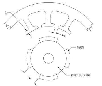
FIGURE 5.25 Inner-rotor tooth shapes.
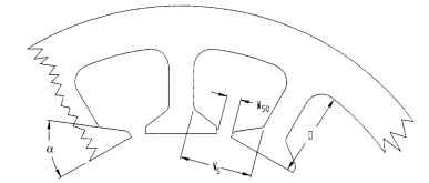
FIGURE 5.26 Inner-rotor tooth proportions.
Structural Magnetic Materials. There are some parts of the motor magnetic circuit that generally wind up being used for mechanical structural purposes as well. The outer-rotor motor in Fig. 5.23 has a rotor yoke which is used to contain the magnets as well as serve as a flux path. The inner-rotor motor in Fig. 5.24 has a rotor core to which the magnets are bonded. This core serves as the magnetic rotor yoke as well as the means of attaching the output shaft to the magnets. These materials are usually a magnetically soft steel of the type ANSI CRS 1008 to 1026. It is not a requirement that theses parts be laminated because the direction of the flux in them does not change; therefore, there are no core losses. A typical magnetization curve of this material is shown in Fig. 5.27.
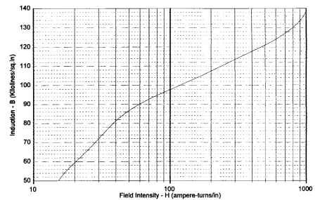
FIGURE 5.27 Unannealed 1020 CRS housing material.
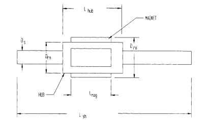
Rotor Inertia. The following method for calculating rotor inertia is based on the assumption that all parts of the rotor rotate around the center of the shaft.
For the outer-rotor motor in Fig. 5.28, calculate the inertia of each part separately, then add the parts together for the total rotor inertia. First, calculate the inertia of the shaft:
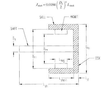
FIGURE 5.28 Outer-rotor inertia.
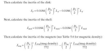
TABLE 5.6 Densities of Common Magnetic Materials
| Material | lb/in3 | Density oz/in3 |
g/cm3 |
| Bonded ferrite | 0.134 | 2.14 | 3.71 |
| Sintered ferrite | 0.177 | 2.83 | 4.90 |
| Alnico | 0.264 | 4.22 | 7.31 |
| Samarium cobalt | 0.302 | 4.83 | 8.35 |
| Neodymium-iron-boron | 0.271 | 4.34 | 7.50 |
