6.4
The following procedures provide methods of calculating the performance of single-phase induction motors. Three types of single-phase motors are discussed. They are the split-phase, capacitor-start, and permanent-split-capacitor (PSC) motors. The general procedure for calculating these types of motors is identical. Differences lie in the starting conditions on the split-phase and capacitor-start motors. The PSC motor has additional performance calculations that have to be taken into account.
A single-phase motor by itself has a field that pulsates north-south, south-north through the rotor but does not revolve. The rotor bars are not cut by any flux lines. No voltage or current is induced, and the motor will not start. Auxiliary means are necessary to start the motor. This can be accomplished by adding an auxiliary winding in space quadrature and by varying reactance by varying turns and resistance or by adding capacitance or inductance. The split-phase motor contains an auxiliary winding that is displaced in space by 90° electrical and connected in parallel with the main winding. Typically, the auxiliary winding has 60 to 70 percent of the number of turns of the main winding and is approximately three gauges smaller in wire size. Once the motor reaches 75 to 80 percent of synchronous speed, the auxiliary winding is switched out and the motor runs on the main winding only. The capacitor-start motor is wired in the same manner as the split-phase motor and also contains a switch that cuts out the auxiliary winding after starting is achieved; however, a capacitor is placed in series with the auxiliary winding. The capacitor creates a displacement of the currents in the two windings by 90° in time. This displacement produces the effect of a rotating field and thus a starting torque. The capacitor-start motor produces a greater locked rotor torque than its split-phase counterpart. The locked rotor torque is proportional to the product of three main factors: (1) the sine of the phase displacement angle between the currents in the two windings, (2) the product of the main-winding current multiplied by the auxiliary-winding current, and (3) the number of turns in the auxiliary winding. All three of these factors are more favorable in the capacitor-start motor.
In a PSC motor, the auxiliary winding and capacitor are used continuously. No starting switch or relay is needed. These motors are generally used only in special-duty applications. A PSC motor is well suited for fan applications because of its ability to vary its speed. The continuously running capacitor improves performance by creating magnetic field conditions similar to those of a polyphase motor. These balanced field conditions can be obtained at only one load point. Generally, the designer will balance the motor at full load.
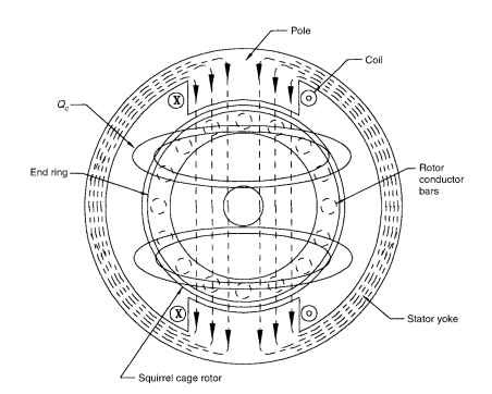
The following calculation procedure for the single-phase motor is based on the cross-field theory by P. H. Trickey. Figure 6.26 shows a single phase motor with a cross-field flux. At standstill, the pulsating stator field induces a rotor current that induces an in-phase component of rotor flux. When the rotor is moving, according to Flemming’s law, a current is induced which produces quadrature rotor flux <|).The in-phase rotor current interacting with <) produces useful motor torque. At a standstill there is no cross-field flux, and therefore no torque. Both the revolving-field (as discussed in Sec. 6.2) and the cross-field theories demonstrate that single-phase motors
will not start by themselves. Auxiliary methods must be employed. This section covers several of them. Calculations can begin by solving for the rotor and stator geometrical constants, plus the winding factors for the motor. Next, the slot, zigzag, end, and belt leakage reactance can be calculated and summed. The open-circuit reactance can then be calculated, along with the flux, mmf drops, and saturation factors. Primary and secondary resistance can be calculated using properties of the wire for the primary resistance and using dimensions and properties of the rotor bar material for the secondary resistance. Calculation of the iron loss and an educated estimation of the friction and windage loss will round out the preliminary calculations. Once all of the preceding values of the motor have been calculated, one can begin the performance calculation procedure. Magnetizing, secondary, and secondary cross-field current can be calculated. The overall performance of the motor, such as its torque, efficiency, and power factor, can be evaluated. As previously discussed, the single-phase motor inherently has zero starting torque. Calculation procedures are given for evaluating the starting conditions for the split-phase and the capacitor-start motor at the end of the performance calculations.


FIGURE 6.26 Single-phase motor with cross-field flux (main pole).
Polyphase induction motor calculations follow in a manner similar to that of the single-phase routine. As with the single-phase motor, once all of the motor constants and reactance values are calculated, the performance of the motor can be evaluated.
The calculation procedure for PSC motors will give performance results at any load. The procedure outlined for calculating the performance of a PSC motor is similar in nature to that for a two-phase motor. First, calculate the reactances and resistances of the motor, just as for the polyphase motor. Next, calculate a series of motor constants based on the reactances and resistances. The currents in the motor can be solved from these constants. Finally, the performance of the motor can be evaluated. The section later discusses how to proportion the windings and the value of capacitance to obtain near-two-phase motor performance at one desired load point.
