10.9.4
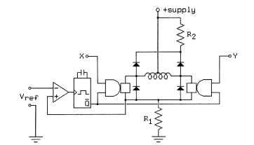
The most common approach to automatically adjusting the duty cycle of the switches in the stepper driver involves monitoring the current to the motor windings; when it rises too high, the winding is turned off for a fixed interval. This requires a current-sensing system and a one-shot, as illustrated in Fig. 10.59.

FIGURE 10.59 One-shot current-sensing circuit.
Figure 10.59 illustrates a unipolar drive system. As with the circuit given in Fig. 10.55, R1 should be as small as possible, limited only by the requirement that the sense voltage provided to the comparator must be high enough to be within its operating range. Note that when the one-shot output Q is low, the voltage across R1 no longer reflects the current through the motor winding. Therefore, the one-shot must be insensitive to the output of the comparator between the time it fires and the time it resets. Practical circuit designs using this approach involve some complexity to meet this constraint.
Selecting the value of R2 for the circuit shown in Fig. 10.59 poses problems. If R2 is large, the current through the motor windings will decay quickly when the higher level control system turns off this motor winding, but when the winding is turned on, the current ripple will be large, and the power lost in R2 will be significant. If R2 is small, this circuit will be very energy efficient, but the current through the motor winding will decay only slowly when this winding is turned off, and this will reduce the cutoff speed of the motor.

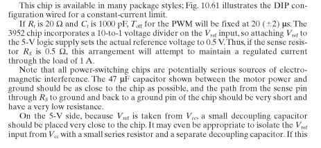
Given the usual safety margins used in selecting power resistor wattages, a better approximation is not necessary.
When designing a control system based on PWM, note that the cutoff time for the
![]()
attached to the one-shot. Ideally, this should be set as follows:
![]()

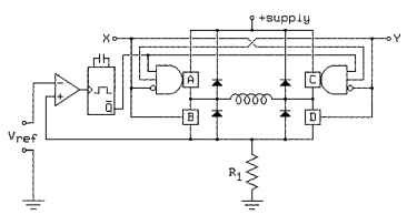
The one-shot current regulator shown in Fig. 10.59 can also be applied to an H-bridge regulator. The encoded H bridge shown in Fig. 10.49 is an excellent candidate for this application, as shown in Fig. 10.60.
Unlike the circuit in Fig. 10.59, this circuit does not provide design tradeoffs in the selection of the resistance in the current decay path; instead, it offers the same selection of decay paths as is available in the original circuit from Fig. 10.49. If the X and Y control inputs are held in a running mode (01 or 10), the current limiter will alter-

FIGURE 10.60 Current-regulated H bridge.
nate between that running mode and slow-decay modes, maximizing energy efficiency. When the time comes to turn off the current through the motor winding, the X and Y inputs may be set to 00, using fast-decay mode to maximize the cutoff speed, while if the damping effect of dynamic braking is needed to control resonance, X and Y may be set to 11.
Note that the current recirculation path during dynamic braking does not pass through R1; as a result, if the motor generates a large amount of power, burnt-out components in the motor or controller are likely. This is unlikely to cause problems with stepping motors, but when dynamic braking is used with dc motors, the current limiter should be arranged to remain engaged while in braking mode.
Practical Examples. SGS-Thompson (and others) L293 (1 A) and L298 (2 A) dual H bridges are designed for easy use with partial-feedback current limiters. These chips have enable inputs for each H bridge that can be directly connected to the output of the one-shot, and they have ground connections for motor power that are isolated from their logic ground connections; this allows sense resistors to be easily incorporated into the circuit.
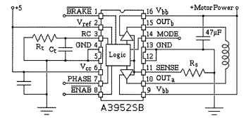
The 3952 H bridge from Allegro Microsystems can handle up to 2 A at 50 V and incorporates all of the logic necessary for current control, including comparators and one-shot.


FIGURE 10.61 H-bridge DIP configuration wired for a constant current limit.
![]()
One of the more dismaying features of the 3952 chip, as well as many of its competitors, is the large number of control inputs. These are summarized in Table 10.17.
In the forward and reverse running modes, the mode input determines whether fast- or slow-decay modes are used during Toff. In the dynamic-braking modes, the mode input determines whether the current limiter is enabled. This is of limited value with stepping motors, but use of dynamic braking without a current limiter can be dangerous with dc motors.
In sleep mode, the power consumption of the chip is minimized. From the perspective of the load, sleep and standby modes put the load into fast-decay mode (all switches off) but in sleep mode, the chip draws considerably less power, both from the logic supply and the motor supply.
One-Shot Feedback Current Limiting (Electric Motors)
Next post: Hysteresis Feedback Current Limiting (Electric Motors)
Previous post: Open-Loop Current Limiters (Electric Motors)
