6.4.2
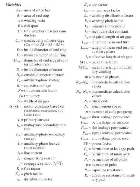
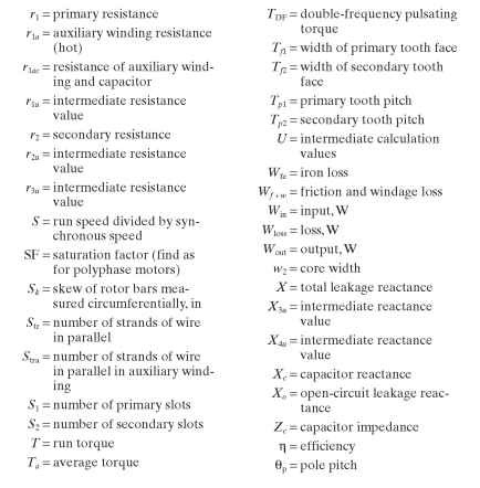
Variables to Calculate
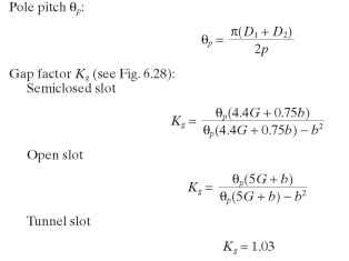
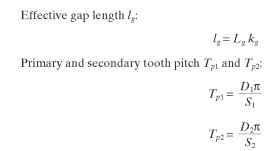
Calculation of Winding and Slot Constants
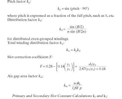
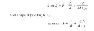
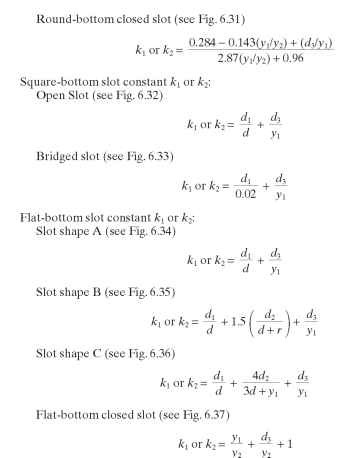
Note: See figures for variable descriptions. k represents the primary (stator) slot constant, while k2 represents the secondary (rotor) slot constant. They are found using the same set of equations, being careful to use the equation which most closely resembles that of the slot in question.
Round-bottom slot constant k1 or k2 (note that Fis different for the two constants): Slot shape A (see Fig. 6.29)
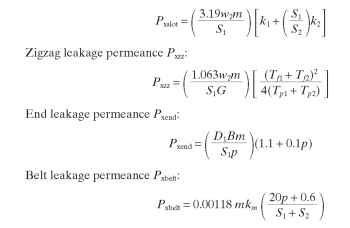
Leakage Reactances Slot leakage permeance Pxslot:

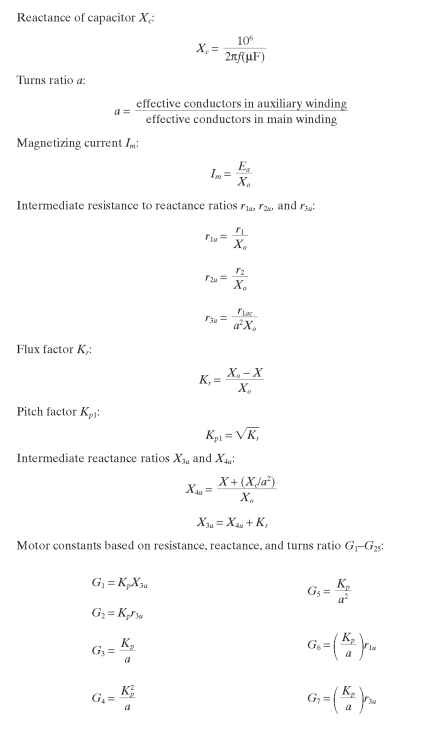
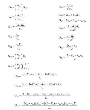
Intermediate Calculation Values
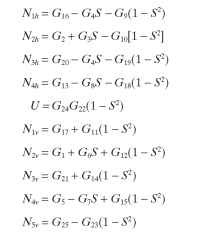
Current Calculations
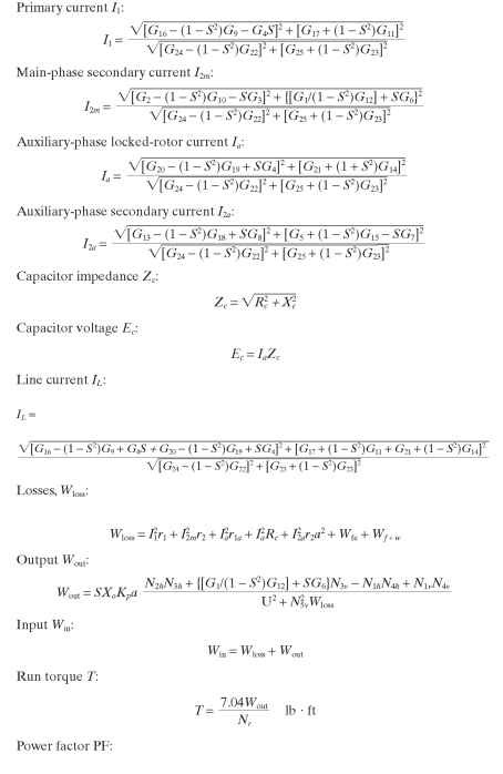
Method for Balancing a PSC Motor. See the single-phase permanent-split-capacitor diagram in Fig. 6.42.
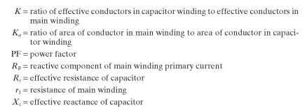
Variables used in the following PSC balancing equations:

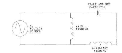
FIGURE 6.42 Single-phase permanent-split-capacitor diagram.
Calculation Procedure
1. Design the main winding to achieve the necessary maximum torque.
2. Calculate the performance as a two-phase motor.
3. Solve for K.
• Ka must be a function of the cubed root of 2 since wire sizes vary in this ratio.
• Assume Ka will be one of these values: 1.26,1.59, or 2.00.
• Set the value of K on the right side of the equation to Ka.
• Solve for K, substitute this value for the assumed value, and perform a second iteration.
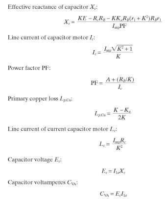
4. Solve for Xc.
5. Design the capacitor from Xc and correct preceding solutions if Rc is too far in error.
6. Calculate the capacitor voltage Ec and the capacitor voltamperes.
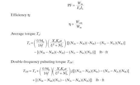
7. Calculate performance equations based on the primary loss, capacitor loss, and power factor calculated.
Use the calculation procedures described in the polyphase section to compute locked-rotor torque. If it is not satisfactory, it may be necessary to reduce K, increase the microfarads, or increase the rotor resistance.
The procedure described will design for the proper value of capacitance to achieve the balance point. However, it is not possible to balance a motor at any load desired. The turns ratio and the capacitance will have to be varied to achieve balanced operation at a desired load point. However, there will be a value of capacitance at any load point that will give a minimum component of backward
field.
PSC Motor Balancing Calculation Equations Power component of main winding primary current A:

A connection diagram of a single-speed PSC motor is shown in Fig. 6.43. For some applications, it is adequate to bring only three leads out of the motor by using an internal connection. The capacitor is often called a run capacitor, even though it remains connected to the motor during both starting and running operation.
PSC motors are commonly used for multispeed applications. Three common connections are shown in Figs. 6.44 and 6.45. Figure 6.44 represents a T-connected motor. Figure 6.45 represents an L-connected motor. Speed is selected by connecting the power source between the common lead and one of the speed leads. The lead colors shown are commonly used, but others may be substituted.
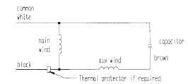
FIGURE 6.43 PSC wiring diagram.
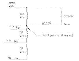
FIGURE 6.44 T-connected multispeed PSC motor.
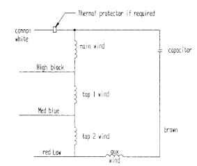
FIGURE 6.45 L-connected multispeed PSC motor.
