4.2.6
In order to determine the resistance and slot fill of the field, the following parameters need to be determined by the designer:
Tpcf = turns of wire per field coil ,Dfw = diameter of field wire
The length of one turn of the field winding must be determined. As with the armature winding, there are three different methods of determining end-turn length for the field.
Field End-Turn Length—Method 1. The mean end-turn length for the field is the average of the length of the shortest turn which is wound tightly across the pole and the length of the turn on the outer edges of each slot. The shortest turn is the straight distance across the pole, and the longest turn is the length of the arc swung across the outer edges of the slots. The field winding mean end-turn length, in inches, is
![]()
where n is 180° converted to radians. The end-turn length will vary slightly with slot fill, winding equipment, and the overhang of the field slot insulation relative to the stack.
In order to use method 2 of determining end-turn length, which is similar to the armature method, you first need to know how the field resistance is determined.
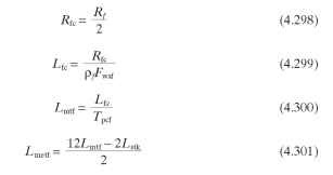
Resistance of Field Windings. The field resistance is the total resistance of two field coils in series. The mean turn length of one field coil, in feet (because wire resistances are given in ohms per foot), is

where pf is the field wire resistance per foot, found from the wire tables for the known wire gauge, and Fwsf is the winding stretch factor, usually 1.02 to 1.10.
The net field resistance is the series combination of two field coils, in ohms:
![]()
Field End-Turn Length—Method 2. As with the armature, this method assumes that you already have a motor and know Rf,Tpcf, Fwsf, and pf (from wire tables). From this, Lmetf can be calculated and then used for calculations for other motors with the same lamination.
The following four formulas give the mean end-turn length for one end of one field turn, in inches.

Field End-Turn Length—Method 3. Measure what loots lite the average end turn on existing motor with the same lamination.
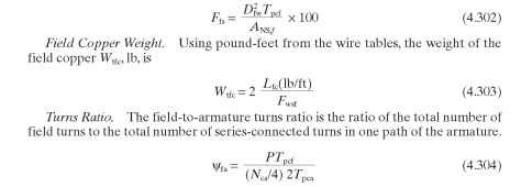
Field (Stator) Slot Fill. The maximum field slot fill depends on the winding equipment. A full slot could be anywhere from 80 to 100 percent. These percentages are greater than for the armature because there is only one coil in the field slot and it is possible to use the slot insulation to extend the area of the slot. The field slot fill is calculated by assuming that the wires are lying side by side as if they were square. Using the outside diameter of the field wire as Dfw (found in the wire tables taking into account insulation thickness), the percentage of winding slot fill is

where P is the number of poles and VVca is the number of active coils in the armature.
This ratio represents the mmf produced by the field in relation to the mmf produced by the armature. If the ratio is too high, the field produces strong mmf, which induces a higher voltage in the commutating coil. This high voltage causes arcing problems during commutation. If the ratio is too low, the armature mmf weakens the pole too much and a loss of torque results. A good range for this ratio is 1.00 to 1.30.
Field Conductors (Electric Motors)
Next post: Magnet Circuit (Electric Motors)
Previous post: Magnetic Paths in the Field (Stator) (Electric Motors)
