10.13.3
The brushless dc motor has one major difference from its brush dc counterpart. All testing including the “simple” back-emf Ke measurement requires that the brushless dc motor be tested with its electronic drive package. The brushless dc motor that uses rare earth magnets can usually outperform its companion drive in the region of maximum torque capability, and there are commutation limits based on motor speed
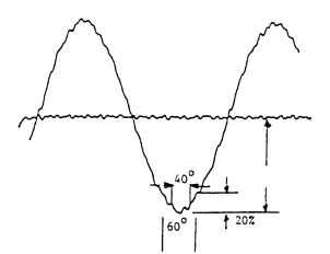
FIGURE 10.110 Static torque function: 36 slots,70° arc,1-slot skew.
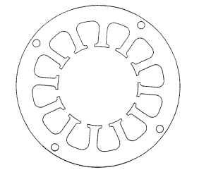
FIGURE 10.111 12-slot lamination.
times the number of commutation switching events per revolution. These two limits shape the torque-speed profile. Figure 10.113 shows a representative torque-speed limit curve for a sinusoidal drive showing these limitations.
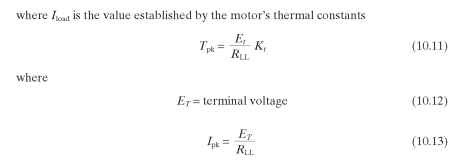
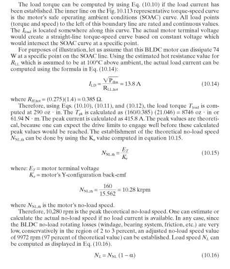
The calculations for establishing the various torque-speed performance points does proceed in the same manner used for a PM brush dc motor, except that the torque and speed limits established for the specific motor-drive combination must be used to limit the calculated values at both ends of the motor torque-speed curve.
The BLDC motor’s torque and speed performance is linear over a major portion of the torque-speed curve as described.
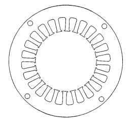
FIGURE 10.112 24-slot lamination.
TABLE 10.23 Basic Comparison Chart
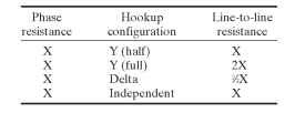

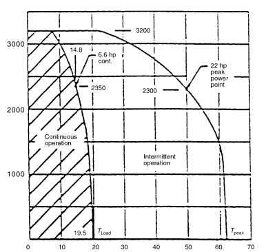
FIGURE 10.113 Typical BLDC motor torque-speed limit curve.
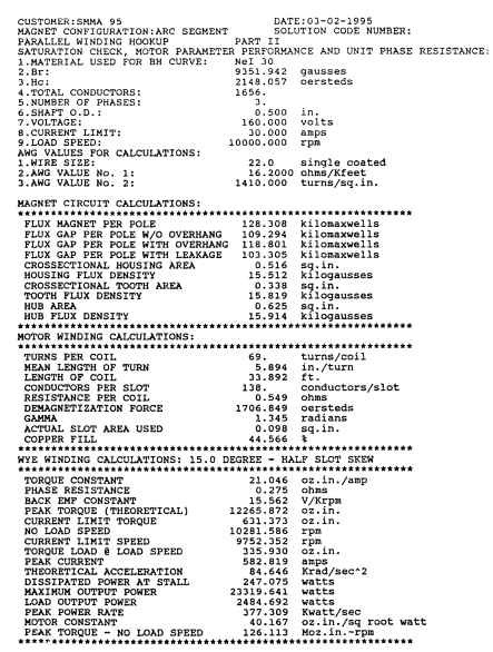
FIGURE 10.114 Example simulation program results.
