3.1.2
The basic dc motor manufacturing process is illustrated in Fig. 3.6. Like ac motors, the first step is producing laminations for the pole piece and armature. The pole-piece lamination is stacked with several other components into a pole piece assembly. The pole piece on dc motors may be of solid steel, as shown in Fig. 3.7. A housing is produced, and when the pole pieces are inserted, it becomes a frame and field assembly, shown in Fig. 3.8. This frame and field assembly is then sent to motor assembly.
Brushes, with other components, are assembled into a brush assembly, as
shown in Fig. 3.9, and this is then assembled on the frame and field assembly.
The armature lamination is stacked into a core, which is then assembled onto a shaft, and copper wire is inserted or wound onto the core. The coils may be connected to the commutator as they are wound, as in Fig. 3.10, or connected after the coils are inserted into the core and shaft assembly, as in Fig. 3.11.This is a completed armature assembly which then goes to final motor assembly.
The frame and field assembly, armature assembly, and miscellaneous parts are then assembled into a complete motor, as shown in Fig. 3.12. The motor is then tested, painted, and packed for shipment.

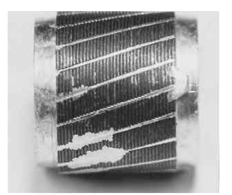
FIGURE 3.4 Rotor casting.

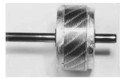
FIGURE 3.5 Rotor assembly.
DC Motor Manufacturing Process Flow (Electric Motors)
Next post: END FRAME MANUFACTURING (Electric Motors)
Previous post: AC Motor Manufacturing Process Flow (Electric Motors)
