5.1.1
Outer-Rotor Motors. These motors are generally used where relatively high rotor inertia is beneficial to system performance. Common applications are computer disk drives and cooling fans. Construction is shown in Figs. 5.6 and 5.7.
The rotor assembly in Fig. 5.6 consists of a flexible magnet with four poles magnetized on it. It is enclosed by a magnetically soft steel cup or housing. A shaft which
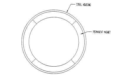
FIGURE 5.6 BLDC outer rotor assembly.
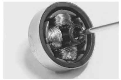
FIGURE 5.7 Outer-rotor BLDC motor rotor and stator assembly.
allows the rotor to turn with respect to the stator is attached to the center of the steel housing.
The stator assembly (Figs. 5.8 and 5.9) consists of a lamination stack with coils of wire wrapped around the pole pieces. This is supported by a mounting base which also contains a bearing support and a control circuit. This motor’s poles are alternately magnetized N-S-N-S.
As the rotor turns, the currents are turned off in one winding set and turned on in the other set by the Hall switch. This results in an S-N-S-N magnetization in which the S poles are induced at the interpoles and the poles where no current exists in the windings. This keeps the rotor turning. A close observation of this structure shows
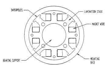
FIGURE 5.8 Outer-rotor BLDC stator diagram.
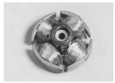
FIGURE 5.9 Outer-rotor BLDC wound stator assembly.
that it is in fact a single-phase motor and, as such, will have rotor positions where there is zero torque. This could result in failure to start. This is overcome by placing interpoles between the wound poles, as shown in Fig. 5.10. The magnet provides some position bias, which always results in rotation when the pole is energized.
Some other methods used to start these single-phase motors are shown in Figs. 5.11 and 5.12. In the case of Fig. 5.11, the reluctance torque produced by the magnet
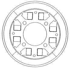
FIGURE 5.10 Outer-rotor motor diagram.
causes the rotor to line up over the pole. When the coils are energized, the field resulting from the energized coil appears to move across the face of the pole in the direction of the wider section of the pole that is closest to the gap. This starts rotation, which may then be maintained by alternately reversing the winding currents. The structure shown in Fig. 5.12 is another method of providing an unbalanced magnetic circuit which causes the rotor to have a preferred resting position in the unen-ergized state that is different from that of the energized state.
All of the motors just discussed are single-phase motors. Although this is probably the case for most outer-rotor motors, it is quite possible to build a multiphase motor in this configuration, as shown in Fig. 5.13.
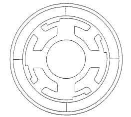
FIGURE 5.11 Stator with reluctance notches.
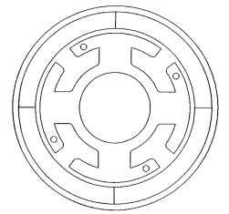
FIGURE 5.12 Stator with reluctance holes.
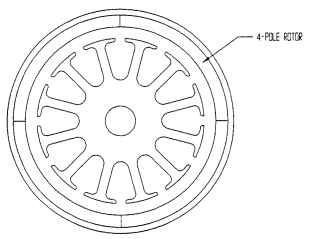
FIGURE 5.13 Multiphase outer-rotor motor.
Inner-Rotor Motors. If one simply inverts the outer-rotor motor diagrammed in Fig. 5.8, the device shown in Fig. 5.14 is generated.This is also a single-phase device, and it would operate in the same fashion as the outer-rotor motor.
Some observations need to be made about these motors. The outer-rotor motor has much more magnetic material than the inner-rotor device, which means it is capable of more flux when the identical materials are used. It would be necessary to use a higher-energy-product magnet to get the same performance from an inner-rotor motor.
The inertia of the inner-rotor motor is lower because of its smaller rotor diameter. Therefore, it accelerates more rapidly than the outer-rotor motor.
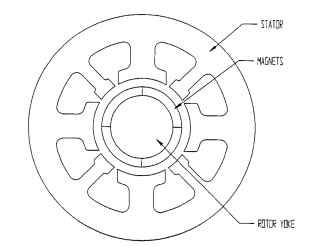
FIGURE 5.14 Single-phase inner-rotor motor.
Most inner-rotor motors have multiple phases in an effort to reduce the starting problems associated with single-phase motors. The stators may have salient poles or distributed windings. Figure 5.15 illustrates a three-phase four-pole salient-pole machine. Here the rotor is a magnetically soft steel core with magnet arc segments bonded to it. As the phases are switched in sequence A-B-C, the rotor moves to line up with the subsequent phase. When the rotor has moved 180° electrical, it is necessary to reverse the current in the windings, starting with phase A, in order to properly polarize the stator poles with respect to the magnet poles.
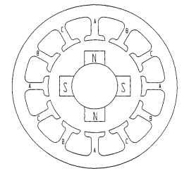
FIGURE 5.15 Multiphase inner-rotor motor.
In order to properly switch the coil currents at the right time and in the right order, the control electronics must know the rotor position. This is usually accomplished by means of Hall-effect devices, encoders, or counter-emf sensing.
Salient-pole machines have inherently high torque perturbation characteristics because of the abrupt permeance changes as the rotor moves from pole to pole. This can be reduced by distributing the windings over several stator teeth per pole. This is illustrated in Fig. 5.16.
Special Configurations—Slotless Brushless Inner-Rotor Motors. One variation of the distributed-winding multiphase brushless motor is the slotless brushless motor. As shown in Fig. 5.17, the winding distribution is similar to that of the stator shown in Fig. 5.16. However, the stator section has no teeth. The advantage of this type of motor is that there are no variations in permeance as the rotor moves. Thus, there are no torque perturbations or cogging. There is, however, a price to be paid. The lack of teeth increases the effective air gap, thereby lowering the available flux.
Another variation is the axial airgap motor. This motor is illustrated in Fig. 5.18. It has a stator with triangular coils (Fig. 5.19) and a disc rotor which is alternately magnetized NS-NS-NS-NS through its thickness. The stator coils (Fig. 5.20) are mounted to a nonmagnetic substrate, while the rotor disc is mounted to a magnetically soft steel. The advantage of this motor is that, like the other slotless motor, it is low cogging, but it also has relatively high inertia.
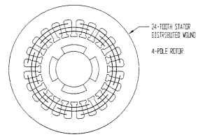
FIGURE 5.16 Inner rotor distributed-wound stator.
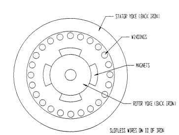
FIGURE 5.17 Inner rotor slotless stator.
Summary. Brushless DC motors can be put into three basic categories according to their structure:
• Outer-rotor motors
• Inner-rotor motors
^ Special-configuration motors
Table 5.1 presents a relative comparison of the inner- and outer-rotor types. This assumes the same physical size motor operating at the same speed and torque.
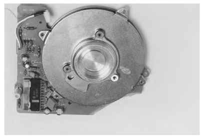
FIGURE 5.18 Axial air gap brushless dc motor.
Basic Configuration of BLDC Motors (Electric Motors)
Next post: Sizing and Shaping the Motor (Electric Motors)
Previous post: ELECTRONICALLY COMMUTATED MOTORS (Electric Motors)
