In recent years, there have been significant advances in the technology for providing central heating in the domestic sector, with the additional benefit of generating electricity at the same time. These are sometimes referred to as home power units (HPUs) and they deliver combined heat and power or CHP. An alternative term is micro-cogeneration. One of the promising systems for homes is based on the Stirling engine.
Micro-CHP
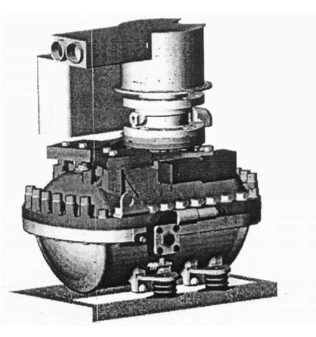
It is interesting how two 19th century technologies, the fuel cell and the Stirling engine, are only now coming into their own. Invented by Robert Stirling in 1816, the engine that bears his name is described as an ‘external combustion engine’. This is because heat is applied to the outside of the unit to heat up a gas within a sealed cylinder. The heat source is at one end of the cylinder, while the cooling takes place at the opposite end. The internal piston is driven by the successive heating and cooling of the gas. When the gas is heated it expands, pushing down the piston. In the process the gas is cooled and then pushed to the heated top of the cylinder by the returning piston, once again to expand and repeat the process. Because of advances in piston technology and in materials like ceramics from the space industry and high temperature steels allowing temperatures to rise to 1200°C, it is now considered a firm contender for the microp-ower market (Figure 7.1).
The operational principle is that a fixed amount of gas is sealed within the engine. In present day engines this is helium or nitrogen. It works on the basis that when the temperature of a specific amount of gas within a fixed volume of space is raised the pressure will increase. At the same time, compressing the gas within the fixed volume will raise its temperature. Heat is applied to the exterior of the engine to achieve this change of state of the gas. Heat can be drawn off the engine at its cool end to provide space heating for a warm air or wet system. Alternatively it can supply domestic hot water. In some cases, the vertical motion of the piston is converted to circular motion to power a generator.
Figure 7.1 Dual chamber Stirling engine.
In the 2 March 2002 issue of the journal New Scientist it reported on a family in the UK operating a WhisperTech Stirling engine currently available from Gastec and Zantingh in The Netherlands. The family were satisfied that the unit served heating and hot water needs .
Figure 7.2 Illustration of the WhisperGen arrangement in a typical house.
Another manufacturer is Victron Energy in The Netherlands. Its Stirling-based system goes under the name of WhisperGen (Figure 7.2). Electricity production is rated at 800 W (800 We) and available heat at 7 kW (7 kWh). It is designed to run on automotive diesel fuel (www.victronenergy.com).
The UK company BG Group is currently conducting trials of a Stirling CHP system under the name MicroGen. At the heart of the system is a unique technology developed by Sunpower in the USA. This consists of a sealed chamber containing a free piston integrated with an alternator. The piston carries the alternator magnets, enabling the production of single phase electricity at 230 volts (50 Hz).
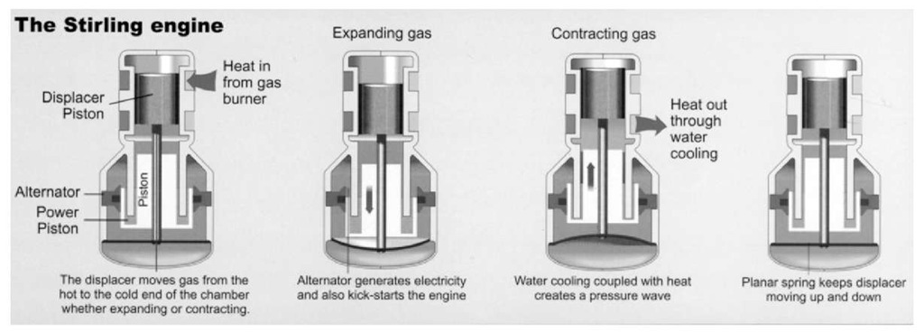
The top of the chamber is heated to 550°C whilst the lower part is cooled to the heating system temperature (usually approximately 45°C) creating the necessary pressure difference in the captive gas. The MicroGen unit is designed to produce 1.1 kW of electricity, which is considered to be adequate for base load domestic requirements. Any further load will be drawn from the grid in the normal way. Because the system is strictly controlled to 50 Hz, it is compatible with mains electricity and therefore can be linked directly to the domestic ring main. It will be possible to feed excess electricity back to the grid. The four phases of the Stirling cycle are explained in Figure 7.3.
On the heating side, the heat which is drawn off by the water coolant is reinforced by heat from the flue gases extracted by a heat exchanger. There is a supplementary heating element in the system for occasions when demand exceeds the output from the engine.
Figure 7.3 Four phases of the Stirling engine cycle.
Figure 7.4 (a) MicroGen Stirling CHP system and (b) prototype of wall mounted unit.
The heat is transmitted to the home heating system. There is a supplementary burner in the system for occasions when heat demands exceeds the output from the engine. All models will be able to reduce their heating output to 5kW when necessary. Future models could be adapted to serve warm air heating systems. Multiple unit systems may also be developed to provide increased power and heat.
The Stirling engine is a sealed unit, so the servicing requirements for the Microgen appliance are the same as they would be for a condensing boiler. Another advantage of the system is that it is quiet in operation.
It is expected that pilot units will be installed late 2003/early 2004 and the Microgen appliance should be commercially available late 2004. The cost estimate is that the system will pay back any additional cost over and above any conventional boiler in 4-5 years.
A note of caution. At the moment it is up to a distributed network operator (DNO) whether or not supply from a domestic CHP unit will be accepted by the grid. There is one of a number of anomalies which the government will have to resolve if its enthusiasm for CHP is to be matched by actions. Hopefully the UK will follow the example of other countries and introduce ‘net metering’. This means that the meter credits the units generated by the CHP unit at the same rate as the unit cost of power from the grid. Discrepancies in the market across the European Union will be rectified by 2010 by which date the market has to be liberalized. In the meantime, the main benefit of producing on-site electricity is in the avoided cost of importing electricity from the grid at market prices.
Despite the current regulatory problems, the UK Department of Environment Farming and Rural Affairs is optimistic about the prospects for micro-CHP or ‘micro-cogeneration’, estimating the potential domestic market to be up to 10 million units. With the opening up of the energy markets, micro-CHP is likely to become a major player in the energy stakes, accounting for some 25-30 GW of electricity (GWe). One of the factors favouring this technology is that it can be up to 90 per cent efficient and result in a reduction in total carbon dioxide emissions of up to 50 per cent when compared with the separate production of heat and energy. Large power stations are about 40 per cent efficient. Add to this line losses of 5-7 per cent and it is obvious there is no contest.
In summary, the advantages of micro-CHP or micro-cogeneration are
• It is a robust technology with few moving parts.
• Maintenance is simple (on average once a year).
• Since there is no explosive combustion, the engine produces a noise level equivalent to a refrigerator.
• It is compact with a domestic unit being no larger than an average refrigerator.
• It operates on natural gas, diesel or domestic fuel oil. In the not too distant future machines may be fuelled by biogas from the anaerobic digestion of waste.
• The efficiency is at least 90 per cent compared with 60 per cent for a standard non-condensing boiler.
• Unlike a boiler it produces both heat and electricity, reducing energy use by about 20 per cent and saving perhaps £200-300 on the average annual electricity bill.
• It can be adapted to provide cooling as well as heat.
The UK government is keen to promote this technology and it is always worth checking if grants are available. The best source of advice is the Energy Saving Trust (www.est.org.uk).
Heat pumps
Another cogeneration technology which is predicted to make an impact on the domestic market centres on heat pumps. The advantage of this technology is that it can provide both heating and cooling for the same cost as a conventional central heating system. As the technology is still relatively unknown in the UK it is worth some explanation.
The most efficient is the geothermal heat pump (GHP) which originated in the 1940s and draws its heat from the ground. For this reason it is also called a ground source heat pump. This is another technology which goes back a long way but which is only now realizing its potential as a technology for the future.
Heat pump mechanism
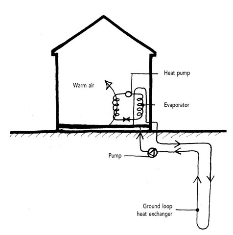
Below a certain depth, say 3 m, the ground maintains a constant temperature of 10-12°C winter or summer. A heat pump extracts some of this warmth and amplifies it to a temperature suitable to supplement space heating (Figure 7.5). There are two major elements in the system:
(1) A high density polyethylene pipe filled with a water and anti-freeze mix buried in the ground causing it to act as a heat transporter. The pipe is laid in a U-configuration either vertically or horizontally. The horizontal type is most common in residential situations where there is usually adequate open space and because it incurs a much lower excavation cost than the alternative.
(2) The heat pump mechanism has the following components: An evaporator coil
A compressor A condenser coil An expansion valve.
Figure 7.5 Heat pump mechanism.
The operation of the heat pump cycle is:
(1) Liquid refrigerant is forced through an expansion valve.
(2) As the refrigerant leaves the expansion valve it is subject to a loss of pressure.
(3) This causes it to evaporate which, in turn, causes it to remove heat from the water in the ground loop pipes which are wrapped around the evaporator coil.
(4) The water leaving the evaporator casing is cooled ready to pick up more heat from the ground.
(5) The refrigerant is now a gas which next passes through the compressor.
(6) The consequent increase in pressure causes the refrigerant vapour to condense at a fairly high temperature.
(7) As the vapour condenses it releases the heat it absorbed during the evaporation phase which heats up the condenser coil to up to 65°C. At this temperature it provides a useful source of heat to supplement a central heating on domestic hot water system.
Heat pump in cooling mode
A reversing valve enables a heat pump to become a source of cooling in summer. In the cooling mode a GHP is transformed into a refrigerator. Water circulating in the earth loop is warmer than the surrounding ground.
Figure 7.6 Ground source heat pump layout.
It therefore releases heat to the ground, cooling in the process. The cooled water then passes through a heat exchanger in the heat pump. Within the heat exchanger, refrigerant gas heated by a compressor releases its heat to the water which then begins its travel to release heat to the ground. The refrigerant having released its heat energy becomes a cold gas after passing through an expansion valve which is used to cool air or water (Figure 7.6).
In a ducted air system, the heat pump’s fan circulates warm air from the building over the coils containing the cold refrigerant. The resultant cooled air is then blown through the ductwork of the building. The cold refrigerant in the air coil picks up heat energy from the building and then travels to the compressor where it again becomes a hot gas and the cycle starts again. In passing, it is worth stating that insulation keeps heat out as well as in, so has a cooling value in summer.
The main benefit of this technology is that it uses up to 50 per cent less electricity than conventional electrical heating or cooling. A GHP uses one unit of electricity to move between three and four units of heat from the earth. This is described as a coefficient of performance (COP) of 3 or 4:1. The theoretical ultimate COP for heat pumps is 14. In the near future a COP of 8 is likely.
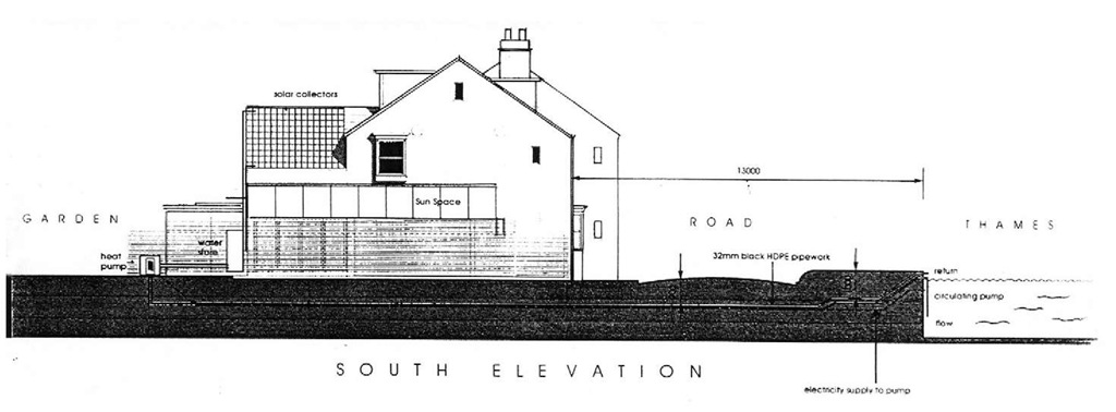
Usually the lowest cost option is to use water in a pond, lake or river as the heat transfer medium. Running water is preferable. The supply pipe is run underground from the building and coiled into circles at least 1.75 m below the surface. An architect in Oxford has recently received permission from the Thames Water Authority to use the river for a water source heat pump. This is now in operation at Osney Island. This is an important breakthrough for a technology which is still regarded with suspicion by water authorities fearing, no doubt, that rivers will freeze over (Figure 7.7).
An alternative to ground or water source heat pumps are the air source heat pumps which are becoming increasingly efficient. In fact, milder winters in the UK mean that inverter speed controlled compressors make air source heat pumps more efficient than ground source heat pumps. This version of the heat pump is mainly used to serve ducted air systems. There are very few available which operate wet underfloor heating systems. However, due to the absence of extensive external works, air source heat pumps are much cheaper than ground source systems.
Variations
Rather than using electricity to power the compressor and fans, there is the prospect that natural gas or biofuel could be used to heat a Stirling engine to work the compressor and generate electricity for the fans. The excess heat could heat the building or provide domestic hot water.
Figure 7.7 Water sourced heat pump at architect’s own house in Oxford.
Another application is in conjunction with heat recovery ventilation (see topic 5). The extract air passes through coils containing a liquid refrigerant which picks up the exported heat. On the ventilation side of the system the refrigerant is condensed releasing heat to the interior. The situation can be reversed when the requirement is for cooling.
Economics
In terms of capital cost, it is still the case that heat pumps are at a disadvantage as against fossil fuel technologies. For example, the cost of a ground source heat pump in the UK is at present two to three times that of a conventional fossil fuel boiler. In the case of a resistive electric installation like electric underfloor heating the cost disparity is even greater. It is in running costs that the advantages are to be found. In more recently built well-insulated homes with good thermal mass in the UK it is possible to achieve revenue savings as compared with mains gas, especially when savings in maintenance costs are factored in.
Note. A heat pump was installed in the Millennium House, Building Research Establishment, Garston, Watford. This was the subject of a BBC TV documentary in 1999. The house may be viewed by appointment, Tel. 01923 664400. This was an installation by GeoScience Ltd of Falmouth (www.geoscience.co.uk).
Stop press. The UK Government has now included heat pumps in its range of technologies eligible for grants under the ‘Clear Skies’ programme.
Evaporative cooling
Most of this topic has been concerned with the question of retaining warmth within the home. As stated above, the prediction of climate scientists is that there will be an increased incidence of extremely high temperatures. Already it is known that the year 2002 was the second warmest year on record, so attention will increasingly be focused on cooling.
For several millennia it has been known that evaporating water reduces air temperature in its vicinity. A fountain in the centre of a Roman ‘executive’ house was not just decorative, it also provided cooling. As hot air hits the cool surface of a pond it causes some evaporation. Heat is transferred from the water to the water vapour causing cooling in the process; the same as the cooling function of evaporating perspiration on the human body. A fountain causes this process to accelerate. So, an open leisure pool in the garden will do more than just provide relaxation, it will also offer relief during extreme heat episodes.
A final note: there is a growing fashion for extending terraces and enlarging patios. It is important to keep hard surfaces to a minimum to limit the extent of run-off for rainwater. If paving slabs are used it is advisable to space them to allow water to drain into the ground. This improves the micro-climate as well as reducing pressure on water treatment plants. Best of all, use recycled slabs.
Fuel cells
Few doubt that the fuel cell will be the ultimate power source of the future and it is already available for the domestic market. So, what is it?
A fuel cell is an electrochemical device that produces electricity in a way that is similar to a battery. But, unlike a battery, it gets its energy from a continuous supply of a fuel – usually hydrogen. It could be conceived as an electrochemical internal combustion engine since the process of creating electricity generates considerable heat. This makes it ideal as a CHP option. Technically it is a reactor which combines hydrogen and oxygen to produce electricity, heat and water. It is a robust technology, quiet in operation, with few moving parts and therefore minimum maintenance requirement and emitting no pollution. The next question is: Where does the hydrogen fuel come from? The answer: from natural gas. Methane is rich in hydrogen which can be extracted by means of a reformer unit. In due course, the electricity needed to split water to release the hydrogen will come from renewable sources, which will make this the ultimate zero pollution power plant.
According to the New Scientist (25 November 2000 p. 3), ‘Within a couple of years, fuel cells will provide electricity for homes and offices. The source of hydrogen will be natural gas which, if cheap enough, will allow fuel cells to undercut today’s combination of heating boiler and mains electricity’. That was a little optimistic as regards the timescale. Nevertheless, International Fuel Cells (US) has been testing a cell producing 5-10 kW of electricity and hot water at 120-160°C for central heating. It plans to be on the market in 2003. In the same year, the US company Plug Power is to market the ‘GE HomeGen 7000′ domestic fuel cell worldwide.
According to Kevin Kendall, a chemist from the University of Keele, ‘Millions of home owners replace their gas-fired central heating systems in Europe every year. Within 5 years they could be installing a fuel cell that would run on natural gas …. Every home could have a combined heat and power plant running off mains gas’. That was said in March 2000, so, only 2 years to go from the time of writing (New Scientist, 18 March 2000).
Within the next decade it is predicted there will be a dramatic growth in the use of fuel cells in both static and mobile applications. It may not be a technology for the moment but almost certainly it will come to have a major role in the domestic CHP market.
It has taken since 1839, when Sir William Grove invented the technology, for the fuel cell to be recognized as the likely principle power source of the future. It is the fuel cell that will be the bridge between the hydrocarbon economy and hydrogen-based society. David Hart who is head of fuel cells and hydrogen research at Imperial College has no doubt about the possibilities for fuel cells:
If fuel cells fulfil their potential, there’s no reason why they shouldn’t replace almost every battery and combustion engine in the world.
There is still considerable potential for improvements in the efficiency of fuel cells since they are not dependent upon heat per se, but on electro-chemical conversion, which means they are not limited by the Second Law of Thermodynamics.
In the USA, there is considerable activity in fuel cell development, not least because of the Department of Energy’s upbeat stance over the technology. ‘The vision is staggering: a society powered almost entirely by hydrogen, the most abundant element in the universe … The overall goal of the DOE is to replace two to four quads of conventional energy with hydrogen by the year 2010, and replace 10 quads per year by 2030. A quad is the amount of energy consumed by one million households’ US NREL.
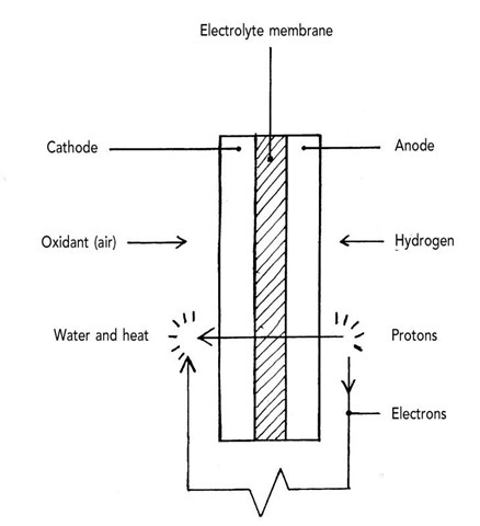
To explain the operation of a fuel cell the polymer electrolyte membrane fuel cell serves the purpose. Sometimes called the proton exchange membrane fuel cell (PEMFC in either case), it is also referred to as the solid polymer fuel cell. This is one of the most common types of cell being appropriate for both vehicle and static application. Of all the cells in production it has the lowest operating temperature of 80°C. The cell consists of an anode and a cathode separated by an electrolyte, usually teflon. Both the anode and cathode are coated with platinum which acts as a catalyst. Hydrogen is fed to the anode and an oxidant (oxygen from the air) to the cathode. The catalyst on the anode facilitates a reaction causing the hydrogen to split into its constituent protons and electrons. The electrolyte membrane allows only protons to pass through to the cathode, thereby setting up a charge separation in the process. The electrons pass through an external circuit creating useful energy at around 0.7 V, then recombine with protons at the cathode to produce water and heat (Figure 7.8). To build up a useful voltage, cells are stacked between conductive bipolar plates, usually graphite which have integral channels to allow the free flow of hydrogen and oxygen (Figure 7.9).
A variation on this theme is the solid oxide fuel cell. This operates at high temperature, about 800°C. Its great virtue is that it can run on a variety of fuels and its high temperature enables it to break down impurities. It is capable of a wide range of power outputs from 2 to 1000 kW. David Hart believes that, ‘solid oxide fuel cells are expected to have the widest range of applications. Large units should be useful in industry for generating electricity and heat.
Figure 7.8 Polymer electrolyte or proton exchange membrane fuel cell.
Figure 7.9 Fuel cell stack.
Smaller units could be used in homes …‘ (New Scientist Inside Science, ‘Fuelling the future, 16 June 2001).
Main points
• Alternatives to conventional heating are receiving government support including CHP. BGTechnology’s Stirling CHP should be on the market by 2004. Other Stirling systems are currently available including from Powergen.
• Developments in the efficiency of heat pump technology offers the promise of a cost-effective alternative to conventional heating.
• These require specialist installation and expert advice for these technologies can be obtained from the Combined Heat and Power Association and Geoscience for heat pumps.
• Fuel cell technology is progressing in both cost-effectiveness and efficiency. It is almost certainly the prime versatile technology for the medium- to long-term future.
