Automatic Reconstruction Pipeline
After uploading the images to the ARC3D server, no further user interaction is needed, but also not possible. Hence, important prerequisites are high fidelity and robustness on the server part. In order to avoid frustration and multiple uploads at the client side, the server should maximize the chance of obtaining a good 3D result, even from sequences of images that are not perfectly suited for the purpose. This requirement has lead us to the development of a hierarchical, highly-parallelized, and opportunistic 3D reconstruction scheme.
The following sections explain the different steps in the images-to-3D process. Non-technical readers may want to skip these sections and go immediately to Section 4.4. Readers who want to know even more about the technical aspects are referred to [5].
Pipeline Overview
A schematic flowchart of the reconstruction pipeline is shown in Figure 4.5. As usual, rectangles represent procedures or actions. Parallelograms represent data structures. The input of the pipeline is found on the top-left and consists of the set of images the user has uploaded to the server using the upload client. At the bottom right the result can be seen consisting of the dense 3D depth maps (and the corresponding confidence maps, as well as the camera settings, positions, and orientations, which are all not shown in the figure). The ARC3D reconstruction pipeline can be seen to consist of roughly five steps:
1. Global image comparison. The first step computes a set of image pairs that can be used for matching, including the Subsampling and Global Image Comparison steps. In this step, the images are first subsampled (hence the hierarchical nature of the pipeline). Since images can be uploaded in non-sequential order, we have to figure out which images can be matched. This is the task of the Global Image Comparison algorithm, which yields a set of image pairs that are candidates for pairwise matching. Typically, such images will have been taken from nearby viewpoints.
2. Matching. In this step, feature points are extracted on the subsampled images. All possible matching candidates of step 1 are now tried. Based on the resulting pairwise matches, all image triplets are selected that stand a chance to together already yield a successful 3D reconstruction. This step corresponds to the Pairwise and Projective Triplet Matching boxes in Figure 4.5.
3. Self-calibration. The self-calibration algortithm finds the intrinsic parameters of the camera. Image triplets are used because they are the smallest sets of images from which the cameras can be calibrated (assuming extra conditions, e.g., like them having the same internal parameters, including the same focal lengths).
4. Sparse reconstruction. Using the self-calibration results, a sparse reconstruction is computed by triangulating the matching feature points between views. The result subsequently upscaled to full resolution.
5. Dense matching. This step is responsible for the dense matching, yielding a dense depth map for every image.
FIGURE 4.5
Global flowchart of the reconstruction pipeline.
Next, we describe the global characteristics of the ARC3D pipeline, like being hierarchical, opportunistic, and parallelized.
Opportunistic Pipeline
Classic 3D reconstruction pipelines make use of the fact that the set of input images is taken in a sequential manner. This helps the reconstruction process tremendously because only consecutive pairs of images must be matched for 3D reconstruction. Unfortunately the 3D web service described in this topic can not rely on this assumption. Users can upload images in non-sequential order. This has an impact on the matching step, the reconstruction step, and the dense matching step.
Hierarchical Pipeline
In general the quality and accuracy of the resulting depth maps is proportional to the size of the input images. However, computing feature-points and matches on large-scale images is very timeconsuming and not so stable a process. That is why all incoming images are first subsampled a number of times until they reach a typical size in the order of 1,000 x 1,000 pixels. As can be seen in Figure 4.5 most of the processing is performed on these subsampled images. It is only in the upscaling step (at the bottom right) that the result is upgraded from the low-resolution to the higher resolution of the input image. This hierarchical approach combines a number of advantages. First it is more stable and has a higher chance of success than direct processing of the high-resolution images. Indeed, it is easier to find matching features between small images because the search range is smaller and therefore fewer false matches are extracted. The upscaling step receives a very good initialization from the lower levels. This means that only a small search and fast optimization need to be performed.
Parallel Pipeline
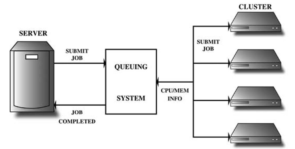
Several operations in the reconstruction pipeline have to be performed many times and independently of each other. Image comparison, feature extraction, pairwise or triplet matching, dense matching, etc., are all examples of such operations. The pipeline is implemented as a Python script which is automatically triggered by the SQL database when a new job arrives. The script has to go through several steps and every step can only be started when the previous one has finished. Inside one step, however, the processing is parallelized. The server on which the script runs has access to a queuing system, as shown in Figure 4.6. When an operation must be performed, the server sends the job to the queuing system which returns a job-id. The queuing system has access to a PC cluster and continuously checks the memory and CPU load of each of the nodes. When a node is free, the job on top of the queue is sent to that node. When the job has finished, the server is automatically notified by the creation of a file, the name of which contains the job-id.
Practical Guidelines for Shooting Images
Introduction
The ARC3D reconstruction process is completely automatic and aims to support all standard consumer cameras on the market. In order to facilitate as many configurations as possible, there are a number of guidelines to follow when shooting images for ARC3D. To assist in the appreciation of these rules, a short and informal explanation of the basic principles behind ARC3D follows.
FIGURE 4.6
Queuing system. The server sends a job to the system. The queue has access to a PC cluster and sends the job to any of the nodes that becomes free.
Humans perceive depth mainly by the means of stereo vision (i.e., our eyes see the same object from slightly different viewpoints). The brain can determine the depth from the disparity (difference in position) of the object between the two views. The brain is aware of the optical configuration of our eyes and is able to provide us with an image with correct depth information. In simple words, the same principle is employed in ARC3D where the different positions of the same scene points in the different images are computed. However, ARC3D is unaware of the optics of the camera used to take the image. These parameters have to be determined in a process known as self-calibration. In summary, ARC3D needs to find and match correspondences between enough views provided the scene contains enough information for self-calibration.
All of this comes down to a number of guidelines to follow when selecting a scene and shooting images. Some of them are stringent and absolutely necessary for a successful reconstruction while others may affect the quality of the resulting output.
Image Shooting
The following guidelines should be observed:
• Shoot multiple pictures of the same scene, but viewed from slightly different directions. Walk with the camera in an arc around the scene, while keeping the scene in frame at all times. Figure 4.7 shows a schematic view of a good sequence of views of a scene.
• (Critical) Keep the same zoom setting for all images in the sequence. The auto calibration assumes that the same setting was used throughout the sequence. If the auto calibration fails, the reconstruction fails. In a future version of ARC3D this condition may be relaxed, due to the specification of the focal length in the EXIF data of modern cameras.
• (Critical) Do not pan from the same location. It is not possible to determine enough 3D information from such a sequence, schematics of which are given in Figure 4.8.
• Do not walk straight towards the scene while shooting images.
• Shoot many pictures to ensure a broad selection, but they must not be panned images. Rule: it is better to shoot too many pictures than too few. As a guide, a minimum of five or six images are required for a good reconstruction. Less than four and the reconstruction will fail. One should keep in mind that only points in the scene that are visible in at least two images can be reconstructed in 3D.
FIGURE 4.7
A diagram of camera positions for a good sequence.
FIGURE 4.8
Diagrams of two bad sequences. Do not pan the camera without translating.
• If one has to stand too far away from the scene to make it fit in the field of view of the camera, the resolution (the detail of the scene) may become too low. In that case one can also start with a part of the scene and very gradually, while in the meantime changing position, include in field of view new parts of the scene. However, one should keep enough overlap between the different pictures (e.g., for every next picture the newly added information is only about 5% with respect to the previous picture).
• Center the camera to one point in the scene. Try to take pictures with the same point in their center, while walking around the scene.
Scene Selection
ARC3D is able to reconstruct a wide variety of scenes, ranging from small artifacts such as pottery and statues, to caves, cathedrals, and natural scenes such as mountain ranges. However, there are a number of issues to keep in mind while choosing a scene:
• (Critical) Avoid purely planar scenes (i.e., scenes that only consist of a single, planar surface). The auto-calibration step of ARC3D requires a scene with enough 3D information and a scene only containing a flat wall will definitely cause the reconstruction to fail. The case study in Section 4.5.2 describes a technique to avoid this.
• Scenery with a lot of intense texture is much more suitable for this 3D technique than scenery with un-textured areas. Examples of areas with low texture are: white walls, sky, human skin, etc. Examples of high texture: paintings, brick wall, irregular surfaces, etc.
• ARC3D is not able to reconstruct moving objects and aims to automatically disregard them. If possible, they should be avoided since they might degrade the result.
• Reflective surfaces can not be reconstructed (e.g., windows, mirrors).
Case Study: Reconstruction of the Mogao Caves of Dunhuang
The Mogao Caves complex is a UNESCO world heritage site and one of the most astonishing Chinese ancient cultural sites [8]. The caves are located in the Gobi Desert, close to the town of Dunhuang, in northwestern China. Situated at an important crossroads of the ancient Silk Road, Dunhuang prospered from wealthy caravans transporting goods between China and western Asia and India. In the 4th century AD, Buddhist monks began to carve out shrines in the rock at Mogao. The Mogao Caves soon became a site of pilgrimage and, promoted by rich merchants exploiting the Silk Road, turned into one of the greatest collections of Buddhist art in the world. An outside view of the Mogao Caves can be seen in Figure 4.9(a). The caves were carved during a time span of more than one thousand years and show great diversity, both in structural and artistic aspects. A typical early cave from the Northern Wei Dynasty (386-581 AD) contains a central sculptured column, around which monks performed walking meditations. In later caves, the central column was often omitted and more intricately detailed sculptures were added. The Mogao Caves reached their peak during the Tang Dynasty (618-906 AD), with caves number 96 and 130 as the most outstanding examples. They contain 30 meter tall sitting Buddhas. Also the murals have changed their characteristics; from the wild and crude brush strokes of the early caves to the finer details of the later ones. Today, 492 caves have been preserved, containing a total of 45,000 square meters of murals. We were invited to the Mogao Caves to demonstrate the 3D reconstruction capabilities of ARC3D.
FIGURE 4.9
Mogao caves in Dunhuang, China. (a) A view of the mountain wall in which the Mogao Caves are carved. In the front is cave 96, containing one of the enormous sitting Buddha statues. Entrances to more regular caves (cave 322 among them) can also be seen. (b) Mogao cave 322, facing the west wall.
In more than one way, these caves pose enormous challenges to 3D capturing. As has already been described, some of these caves are very high and many parts are therefore difficult to reach. Moreover, the caves with a central Buddha often leave a small space between the statue and the cave walls. Add to that the importance of capturing all the omnipresent murals and sculptures of about 500 caves, and the need for a very easy to use and flexible method becomes evident. The local archaeological team is therefore on the lookout for techniques that may work for their site.
As a first test case, we modeled the largest part of one cave. What follows is a description of the work flow, from image acquisition to post-processing, resulting in a mostly complete model of the cave.
3D Reconstruction of Mogao Cave 322
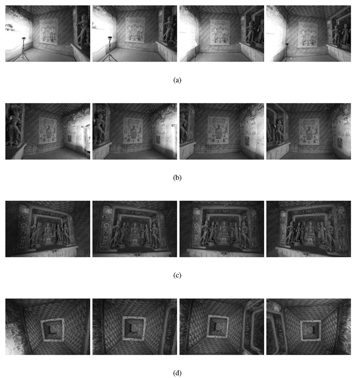
Mogao cave 322 can be seen in Figure 4.9(b). This is a typical Tang Dynasty cave with a square floor of roughly 4×4 meters and a tapered roof. The cave is supposed to reflect vitality, mirroring the rising power and prosperity of the empire. The west wall is what appears in front upon entering the cave. A doubly recessed niche contains a central Buddha in Lotus position flanked by his Disciples, Bodhisattvas and Devarijas. These seven statues are mostly original. The south and north walls (Figure 4.10(a) and Figure 4.10(b)) are both flat and contain exquisite murals. The south wall depicts a preaching scene while the north features the Amitabha Sutra. The thousand Buddhas motifs covering the slanted roof (Figure 4.10(d)) as well as parts of the walls are painted in a two-dimensional, periodic pattern.
This cave lends itself well to 3D reconstruction. Since the core part of ARC3D consists of automatically finding and matching local features between images, the strong texture covering virtually all parts is very helpful. The murals are completely covering the walls and the roof. Although the thousand Buddhas motif might seem repetitive, each of them is painted separately and contains enough individual characteristics to be robustly matched. In addition, the sandstone and clay materials reflect diffusely, thereby sparing the 3D reconstruction troublesome specular reflections. The main challenge lies in the structural complexity of the statues. There are plenty of fine details and many self-occlusions.
FIGURE 4.10
Input images used for reconstructing Mogao cave 322. For every sequence we show four out of the ten images used as input to ARC3D. (a) The south wall. The light setup can also be seen to the left. (b) The north wall with a mural depicting the Amitabha Sutra. (c) The west wall. (d) The tapered roof.
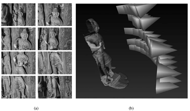
FIGURE 4.11
Reconstructing the Devarija statue. (a) Eight of the images used as input. (b) Camera positions, as computed by ARC3D. Each pyramid represents the viewing direction of the camera. The pyramid basis represents the image plane and the apex is the center of projection.
Image Capturing
A Canon EOS-1Ds Mark III digital camera with a tripod and a 14 mm lens was used to capture the images. Although the camera produces images with 20 mega pixels (MP), only half the resolution was used as input to ARC3D. The small quality gain from 10 to 20 MP does not justify the huge increase in computation time. A wide angle lens (like the 14 mm lens we used) is generally recommended for ARC3D, as long as it does not distort the images too much. The larger field of view allows for more features in the image and may improve the matching process. It also gives a larger depth of field and thus lowers the risk of out-of-focus blurring. Finally, it allows more light to reach the sensor, thus reducing image noise. The cave contains no light source other than the sparse daylight emerging from the doorway. To increase the amount of light and to control the shadows, an artificial light source together with a planar diffuser were placed at the entrance (east) wall, as shown in Figure 4.10(a) The cave was reconstructed in five separate sequences: The south, west, and east walls, the ceiling, and a close-up sequence of one of the statues. The west wall was shot by starting close to the south wall and moving the camera parallel to the wall between images, until the other end was reached. Ten images were taken and the whole niche was kept in the field of view for all of them. Some of the images can be seen in Figure 4.10(c). The planarity of the north and south walls could potentially cause the self-calibration stage of ARC3D to break down. To prevent this, parts of the surrounding walls were kept in the field of view for each picture (see Figure 4.10(a) and Figure 4.10(b)). This provided enough out-of-plane information to successfully perform the self-calibration. Also here, ten images per wall were taken. The Devarija statue to the right of the niche was shot by moving the camera in arcs. The tripod was successively lowered between each completed arc as show in Figure 4.11(b). Care had to be taken to ensure sufficient overlap (about 50%) between the images from two successive arcs. For this sequence, 38 images were used of which some can be seen in Figure 4.11(a).
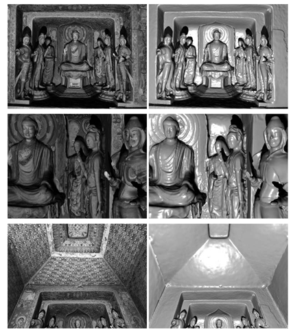
FIGURE 4.12
Views of the reconstruction of Mogao cave. The texture is removed in some of the images to better visualize the underlying structure.
FIGURE 4.13
Close-up views of the reconstruction of Mogao cave 322.
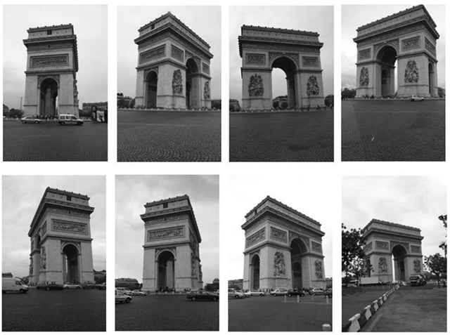
FIGURE 4.14
Eight of the input images used to reconstruct the Arc de Triomphe.

