This section takes a deeper look into what goes into a discovery response packet. This knowledge can help your understanding of what could be going wrong in an AP join process to a WLC. Keep in mind that a sniffer program cannot dissect the information in a discovery packet. The WLC dissects the packet; you can watch this from the WLC CLI using debug lwapp packet enable.
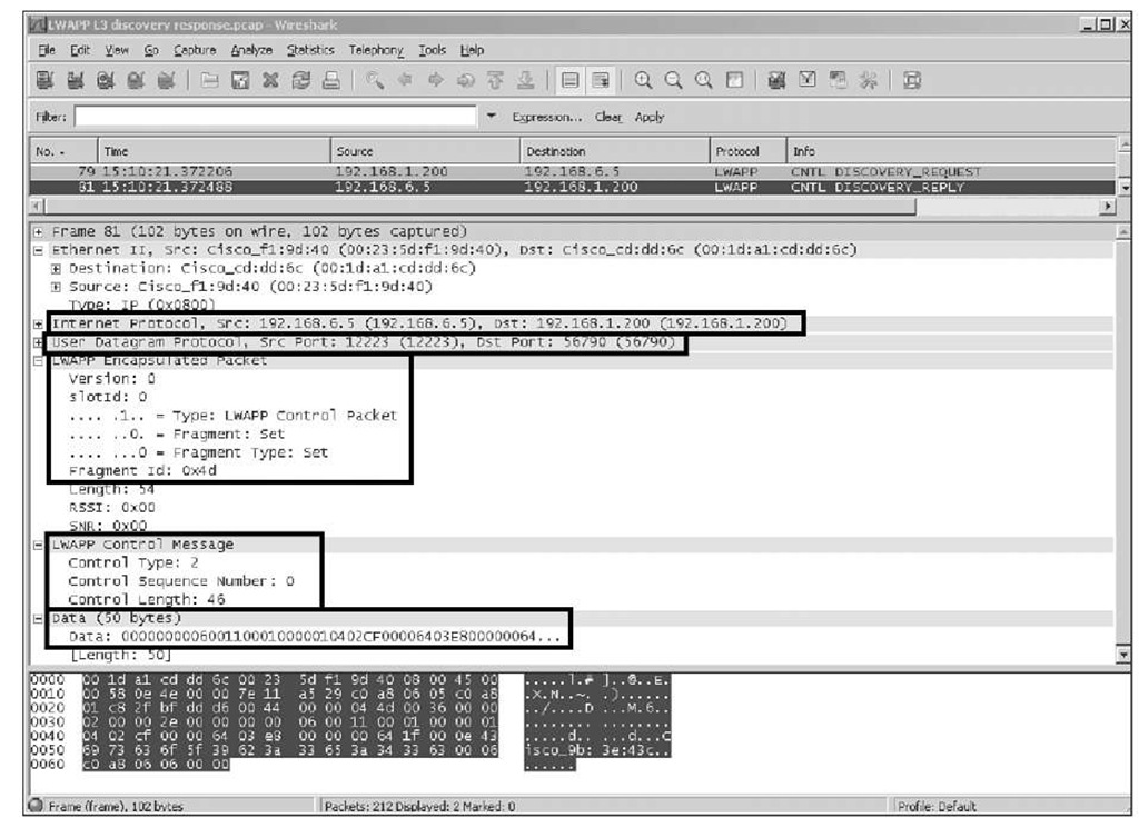
Figure 3-6 shows the most significant fields in a sniffer trace view of a Layer 3 discovery response.
■ IP Header:
Source (Src) is the management IP address.
Destination (Dst) is the AP IP address that sent the discovery request.
DSCP value (not shown) is normally 0×46. If the interface is tagged with a VLAN ID, the 802.1p UP is 7. This is important if QoS policies are enabled on the network. (LWAPP control is quite important.) A 0 value indicates an incorrect QoS configuration on the switching infrastructure.
■ UDP Header:
The source port is 12223.
Destination is the ephemeral port the AP uses. (It remains the same for the duration of the LWAPP session.)
■ LWAPP Header: The first byte is a bit field including the following: Version (2 bits): This is always 0.
Radio ID or SlotID (3 bits): This is 0 for discovery. Control message (1 bit): This is 1 for the LWAPP control.
Fragment (1 bit): This indicates whether the message is a fragment; this is 0 for discovery.
Fragment Type (1 bit): This indicates whether this is the last fragment of the sequence. A 0 indicates it is.
Fragment ID: This is a one-byte counter, increased monotonically for each group of fragments. It is kept by each AP/WLC relationship.
■ LWAPP Control Message Header:
Control type: This will be 2 for discovery response.
Control Sequence Number: This is always 0 for discovery request/response.
Control Length: This is the byte count of the transported data.
■ Data: This contains information about the WLC, including the software version, maximum AP allowed, current number of AP joins, and AP manager IP address.
Figure 3-6 Discovery Response Dissection
Manually Dissecting the Discovery Response
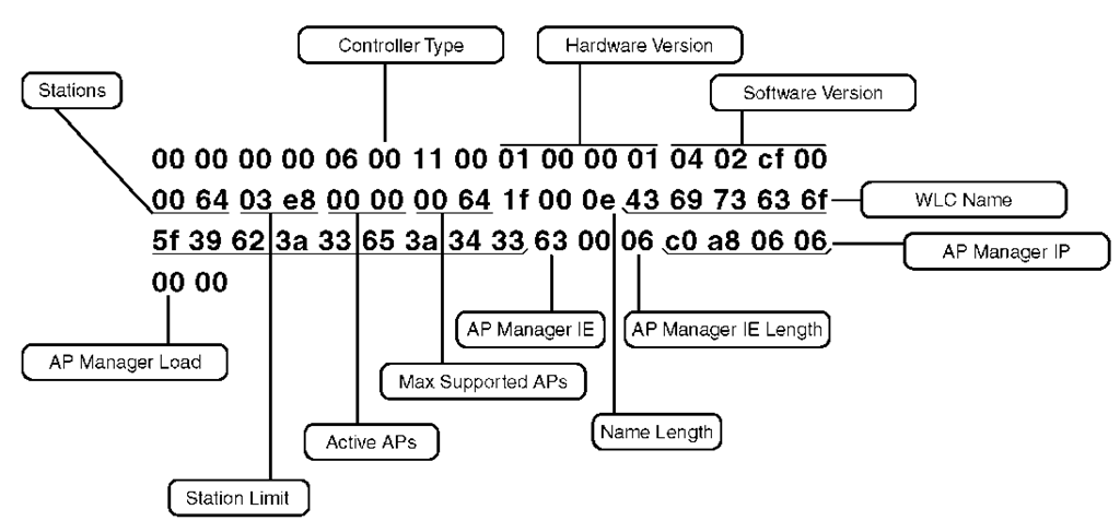
In a discovery response, you can manually analyze the frame if a debugging of LWAPP packets from the WLC is not possible. Consider the example in Figure 3-7.
Figure 3-7 Manual Analysis of Discovery Response Data
In Figure 3-7, you can see the following information in the Data field of the discovery response from the WLC:
■ Controller type: 1-byte value indicating the operating mode of the WLC. 0×00 for a normal WLC.
0×01 for WLC with the master mode set.
As you can see, this WLC is in the normal operating mode.
■ Hardware version: 4-byte value representing the hardware version number of the WLC.
■ Software version: 4 bytes indicating the WLC software version. In the example, it is 04 02 cf 00, which corresponds to 4.2.207.0.
■ Stations: 2-byte value representing the number of clients currently associated with the WLC. In this case, there are none.
■ Station limit: 2-byte value representing the maximum number of stations the WLC supports.
■ Active APs: 2 bytes indicating how many APs are currently joined to the WLC. Zero in the example.
■ Max supported APs: 2-byte value indicating the maximum number of concurrent APs supported on the WLC. This is hardware model dependent. In the example, it is 100 (0×64).
■ Name length: 1-byte value indicating the length in bytes of the WLC system name to follow. (This is important to know if you are analyzing the frame manually.) In this example, the length is 14 bytes.
■ WLC name: 14-byte value in this example indicating the system name of the WLC. This is what will be used to make the join decision. In the example 0x 436973636f5f39623a33653a3433, you can use the sniffer software to translate to ASCII:Cisco_9b:3e:43. This a variable byte length that is not zero terminated.
■ AP manager information element (IE): 1-byte value. This is 0×63, which marks the beginning of the AP manager list. The type is 99 (63 converted to decimal), which indicates it is an IPv4 address.
■ AP manager IE length: The number of AP manager addresses. For LAG WLCs, it is 6 (4 for address + 2 bytes for capacity), as shown in the example. For WLC configurations, you might have multiples of 6 indicating how many AP manager interfaces are configured in the WLC.
■ AP manager IP: 4-byte value indicating the address in hex. In the example, this is c0 a8 06 06, which corresponds to 192.168.6.6.
■ AP manager load: 1-byte value indicating how many APs are joined currently on this AP manager address. It is 0 in the example.
Summary
Using LWAPP for AP/WLC communications allows for many features that are not possible with traditional, standalone AP deployments. Without LWAPP, central administration and management of the wireless network are not possible. When an LWAPP AP boots up, it goes through the LWAPP state machine to eventually reach the run state, where it can start servicing wireless clients. An AP can learn about potential WLCs that it can join in several ways. You can statically configure WLC IPs, use DNS and DHCP, prime the AP on an existing WLC on the network, and even rely on existing APs to tell new APs about their respective controllers. Understanding the LWAPP discovery and join processes used by the APs to register with a WLC is key to troubleshooting any AP join issues.


