The backbone architecture refers to the way in which the backbone interconnects the networks attached to it and how it manages the way in which packets from one network move through the backbone to other networks.
While there are an infinite number of ways in which network designers can build backbone networks, there are really only three fundamental architectures that can be combined in different ways. These architectures are routed backbones (routers that move packets on the basis of network layer addresses), switched backbones (switches that move packets based on data link layer addresses), and virtual LANs (switches that move packets through LANs that are built virtually, not using physical location).
These architectures are mixed and matched to build sets of BNs. Before we discuss these architectures, we first must discuss the way in which network designers think about backbone designs and how to combine them; that is, the different layers of backbones that exist in most organizations today.
Backbone Architecture Layers
Network designers often think about three distinct technology layers1 when they design BNs. The layer closest to the users is the access layer, the technology used in the LANs attached to the BN as described in the previous topic (e.g., 100Base-T, wireless Ethernet) (Figure 8.5). Although the access layer is not part of the BN, the technologies used in the LANs (or access layer) can have major impacts on the design of the backbone.
Figure s.5 Backbone network design layers. LAN = local area network
The distribution layer is the part of the backbone that connects the LANs together. This is the part of the backbone that contains the "TCP/IP gateways" described in next topic. It usually runs throughout one building.
The core layer is the part of the backbone that connects the different BNs together, often from building to building. The core layer is technologies used in the campus network or the enterprise network. Some small organizations are not large enough to have a core layer; their backbone spans only the distribution layer. Other organizations are large enough that they have a core network at several locations that are in turn connected by WANs.
In the sections that follow, we describe the three basic BN architectures and discuss at which layer they are often used. We focus on TCP/IP networks when comparing these architectures. We assume that you are comfortable with the material on TCP/IP in next topic; if you are not, you may want to go back and review the last section of the topic, entitled TCP/IP Example, before you continue reading.
Switched Backbones
Switched backbones are probably the most common type of BN used in the distribution layer (i.e., within a building); most new building BNs designed today use switched backbones. They also are making their way into the core layer as the campus backbone, but routed backbones still remain common.
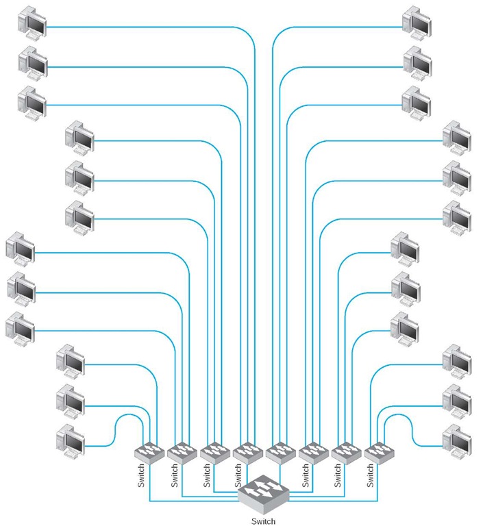
Switched backbone networks use a star topology with one switch at its center. Figure 8.6 shows a switched backbone connecting a series of LANs. There is a switch serving each LAN (access layer) which is connected to the backbone switch at the bottom of the figure (distribution layer). This figure implies that the LAN switches are close to the computers in their LANs and farther from the backbone switch. Most organizations now use switched backbones in which all network devices for one part of the building are physically located in the same room, often in a rack of equipment.
Figure s.6 Switched backbone network design
This form of switched backbone is shown graphically in Figure 8.7. This has the advantage of placing all network equipment in one place for easy maintenance and upgrade, but it does require more cable. In most cases, the cost of the cable itself is only a small part of the overall cost to install the network, so the cost is greatly outweighed by the simplicity of maintenance and the flexibility it provides for future upgrades.
Figure s.7 Rack-mounted switched backbone network design
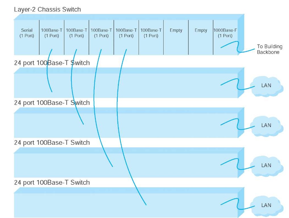
The room containing the rack of equipment is sometimes called the main distribution facility (MDF) or centra! distribution facility (CDF). Figure 8.8 shows a photo of an MDF room at Indiana University. Figure 8.9 shows the equipment diagram of this same room. The cables from all computers and devices in the area served by the MDF (often hundreds of cables) are run into the MDF room. Once in the room, they are connected into the various devices. The devices in the rack are connected among themselves using very short cables called patch cables
Figure 8.8 An MDF with rack-mounted equipment. A layer-2 chassis switch with six 100Base-T modules (center of photo) connects to four 24-port 100Base-T switches. The chassis switch is connected to the campus backbone using 1000Base-F over fiber-optic cable. The cables from each room are wired into the rear of the patch panel (shown at the top of the photo), with the ports on the front of the patch panel labeled to show which room is which. Patch cables connect the patch panel ports to the ports on the switches
Switched Backbones at Indiana University
MANAGEMENT FOCUS
At Indiana University we commonly use switched backbones in our buildings. Figure 8.10 shows a typical design. Each floor in the building has a set of switches and access points that serve the LANs on that floor. Each of these LANs and WLANs are connected into a switch for that floor, thus forming a switched backbone on each floor. Typically, we use switched 100Base-T within each floor.
The switch forming the switched backbone on each floor is then connected into another switch in the basement, which provides a switched backbone for the entire building. The building backbone is usually a higher speed network running over fiber-optic cable (e.g., 100Base-F or 1 GbE). This switch, in turn, is connected into a high-speed router that leads to the campus backbone (a routed backbone design).
With rack-mounted equipment, it becomes simple to move computers from one LAN to another. In the switched backbone design as shown in Figure 8.6, for example,all the computers in the same general physical location are connected to the same switch and thus share the capacity of the switch. Although this often works well, it can cause problems if many of the computers on the switch are high-traffic computers. For example, in Figure 8.6, if all the busy computers on the network are located in the upper left area of the figure, the switch in this area may become a bottleneck.
Figure 8.9 MDF network diagram
Figure 8.10 Switched backbones at Indiana University
With an MDF, all cables run into the MDF. If one switch becomes overloaded, it is straightforward to unplug the cables from several high-demand computers from the overloaded switch and plug them into one or more less-busy switches. This effectively spreads the traffic around the network more efficiently and means that network capacity is no longer tied to the physical location of the computers; computers in the same physical area can be connected into different network segments.
Sometimes a chassis switch is used instead of a rack. A chassis switch enables users to plug modules directly into the switch. Each module is a certain type of network device. One module might be a 16-port 100Base-T hub, another might be a router, whereas another might be a 4-port 100Base-T switch, and so on. The switch is designed to hold a certain number of modules and has a certain internal capacity, so that all the modules can be active at one time. For example, a switch with five 10Base-T hubs, two 10Base-T switches (with 8 ports each), a 100Base-T switch (with 4 ports), and a 100Base-T router would have to have an internal switching capacity of at least 710 Mbps ([5 x 10 Mbps] + [2 x 8 x 10 Mbps] + [4 x 100 Mbps] + 100 Mbps = 710 Mbps).
The key advantage of chassis switches is their flexibility. It becomes simple to add new modules with additional ports as the LAN grows and to upgrade the switch to use new technologies. For example, if you want to add gigabit Ethernet, you simply lay the cable and insert the appropriate module into the chassis switch.


