Fax Relay Example
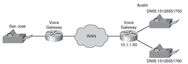
Figure 5-14 shows a topology example for a voice service VoIP and dial-peer configuration of a voice gateway that is configured for fax relay.
Figure 5-14 H.323 Fax Relay Configuration Topology Example
This scenario requires a company’s headquarters in San Jose to be able to fax to its Austin office using T.38 and Cisco fax relay. As a network administrator, your responsibility is to configure the gateway to meet the requirements of the network.
Requirements dictate that you
■ Create two separate dial peers.
■ Configure T.38 fax relay for VoIP dial peers globally.
■ Configure Cisco Fax Relay for a single VoIP dial peer to override the global value.
■ Disable error-correction-mode for a specific dial peer.
■ Specify the fax transmission rate for a specific dial peer.
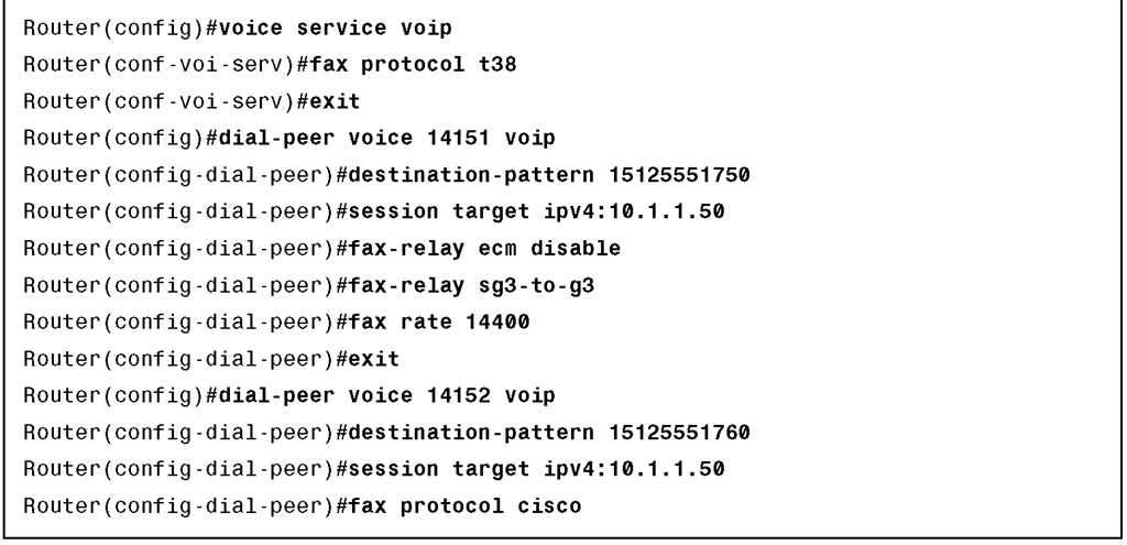
The default fax protocol is set to T.38 using the fax protocol t38 command to the voice service VoIP configuration and then is overridden in dial peer 14152 to cisco. In addition, the fax relay is set to support G3 fax machines and allows a maximum transfer speed of 14.4 kbps for calls to 14151xx numbers.
You can use the following procedure to configure H.323 fax relay.
Step 1. Enter voice-service configuration mode and specify a voice-encapsulation type.
Voice-service configuration mode is used for packet telephony service commands that affect the gateway globally.
Step 2. Specify the global default ITU-T T.38 standard fax protocol to be used for all VoIP dial peers.
Use the fax protocol t38 command and the voice service voip command to configure T.38 fax relay capability for all VoIP dial peers. If the fax protocol t38 (voice-service) command is used to set fax relay options for all dial peers, and the fax protocol t38 (dial peer) command is used on a specific dial peer, the dial-peer configuration takes precedence over the global configuration for that dial peer.
Step 3. Exit voice-service configuration mode.
Step 4. Enter VoIP dial-peer configuration mode.
Step 5. Disable fax-relay Error Correction Mode (ECM).
When this command is entered, the digital signal processor (DSP) fax-relay firmware disables ECM by modifying the Digital Information Signal (DIS) T.30 message. This is performed on DIS signals in both directions so that the ECM is disabled in both directions, even if only one gateway is configured with ECM disabled.
Note This setting is provisioned when the DSP channel starts fax relay and cannot be changed during the fax relay session.
Step 6. Enable the fax stream between two Super Group 3 (SG3) fax machines to negotiate down to G3 speeds.
Example 5-3 illustrates the complete H.323 fax-relay configuration example previously described.
Example 5-3 H.323 Fax-Relay Configuration Example
Configuring H.323 DTMF Relay
DTMF is the tone generated when you press a button on a touch-tone phone. This tone is compressed at one end of a call. When the tone is decompressed at the other end, it can become distorted, depending on the codec used. The DTMF relay feature transports DTMF tones generated after call establishment out-of-band using either a standard H.323 out-of-band method or a proprietary RTP-based mechanism. For SIP calls, the most appropriate method to transport DTMF tones is RTP-NTE or SIP-NOTIFY.
Although DTMF is usually transported accurately when using high-bit-rate voice codecs such as G.711, low-bit-rate codecs, such as G.729 and G.723.1 are highly optimized for voice patterns and tend to distort DTMF tones. As a result, interactive voice response (IVR) systems might not correctly recognize the tones.
To specify how an H.323 or a SIP gateway relays dual-tone multifrequency (DTMF) tones between telephony interfaces and an IP network, use the dtmf-relay command.
You can use the following procedure to configure DTMF relay on a Cisco IOS gateway.
Step 1. Enter dial-peer configuration mode for the appropriate dial peer.
Step 2. Enable DTMF tone forwarding.
The principal advantage of the dtmf-relay command is that it sends DTMF tones with greater fidelity than is possible in-band for most low-bandwidth codecs, such as G.729 and G.723. Without the use of DTMF relay, calls established with low-bandwidth codecs might have trouble accessing automated DTMF-based systems, such as voice mail, menu-based Automatic Call Distributor (ACD) systems, and automated banking systems.
Figure 5-15 and Example 5-4 illustrate a complete H.323 DTMF relay configuration example.
Figure 5-15 H.323 DTMF Relay Configuration Topology Example
Example 5-4 H.323 DTMF Configuration Example
Verifying an H.323 Gateway
Use the show gateway command to verify that an H.323 gateway is operational and to display the current status of the gateway.
Example 5-5 shows a sample report that appears when a gateway is not registered with a gatekeeper.
Example 5-5 show gateway Command with an Unregistered Gateway
Example 5-6 shows a sample report that indicates an E.164 address has been assigned to the gateway.
Example 5-6 show gateway Command with a Registered Gateway

![tmp1D-122_thumb[2][2][2]_thumb tmp1D-122_thumb[2][2][2]_thumb](http://what-when-how.com/wp-content/uploads/2012/03/tmp1D122_thumb222_thumb_thumb.jpg)
![tmp1D-123_thumb[2][2][2]_thumb tmp1D-123_thumb[2][2][2]_thumb](http://what-when-how.com/wp-content/uploads/2012/03/tmp1D123_thumb222_thumb_thumb.jpg)


