H.323 Call Establishment and Maintenance
Although H.323 is based on the concepts of a distributed call control model, it often embodies centralized call control model concepts. Calls can be established between any of these components:
■ Endpoint to endpoint: The intelligence of H.323 endpoints allows them to operate autonomously. In this mode of operation, endpoints locate other endpoints through nonstandard mechanisms and initiate direct communication between the endpoints.
■ Endpoint to gatekeeper: When a gatekeeper is added to the network, endpoints interoperate with the gatekeeper using the RAS channel.
■ Gatekeeper to gatekeeper: In the presence of multiple gatekeepers, gatekeepers communicate with each other on the RAS channel.
H.323 Call Flows
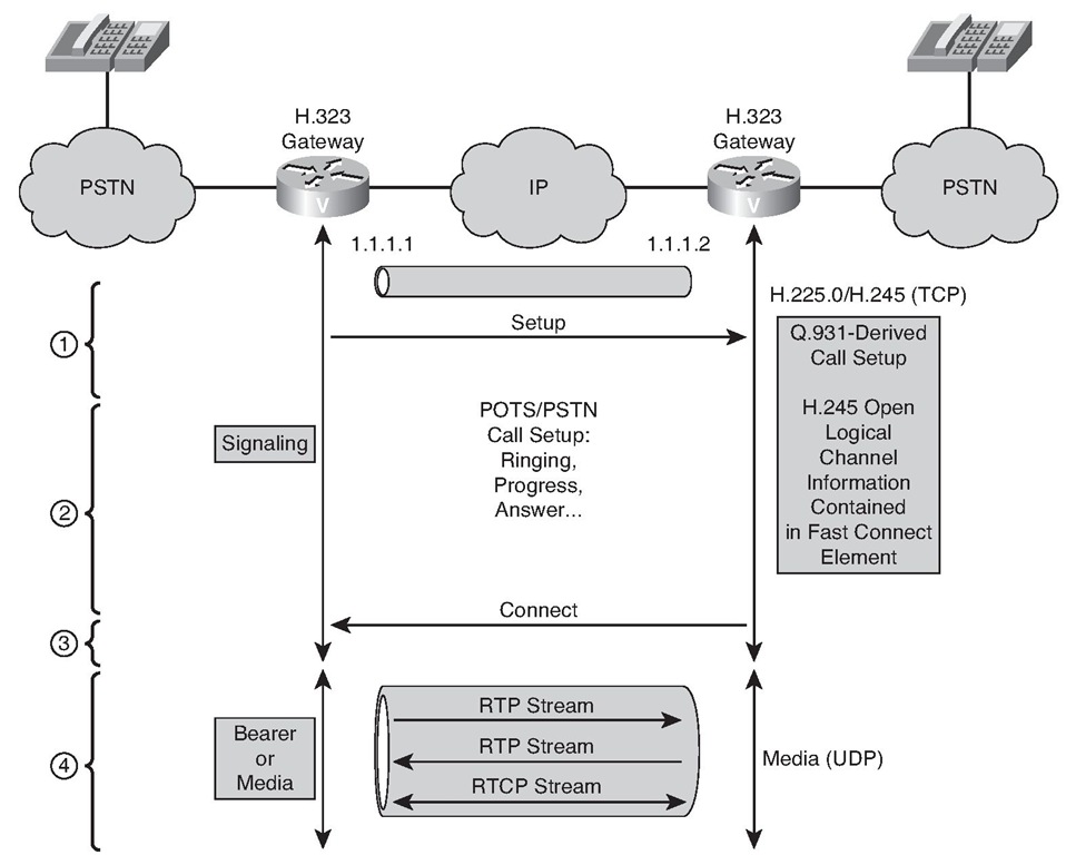
H.323 calls might occur with or without the use of a gatekeeper. Figure 5-9 shows an H.323 basic call setup exchange between two gateways. The optional gatekeeper is not present in this example. Although gateways are shown, the same procedure is used when one or both endpoints are H.323 terminals.
Figure 5-9 H.323 Basic Call Setup
H.323 Basic Call Setup
The flow procedure without a gatekeeper includes these steps:
1. The originating gateway initiates an H.225.0 session with the destination gateway on registered TCP port 1720. The gateway determines the IP address of the destination gateway internally. The gateway has the IP address of the destination endpoint in its configuration, or it knows a Domain Name System (DNS) resolvable domain name for the destination.
2. Call setup procedures based on Q.931 create a call-signaling channel between the endpoints.
3. The endpoints open another channel for the H.245 control function. The H.245 control function negotiates capabilities and exchanges logical channel descriptions.
4. The logical channel descriptions open RTP sessions.
5. The endpoints exchange multimedia over the RTP sessions, including exchanging call quality statistics using RTP Control Protocol (RTCP).
H.323 Fast Connect Call Setup
Figure 5-10 shows an H.323 setup exchange that uses the Fast Connect abbreviated procedure available in version 2 of ITU-T Recommendation H.323.
The Fast Connect procedure reduces the number of round-trip exchanges and achieves the capability exchange and logical channel assignments in one round trip.
The Fast Connect procedure includes these steps:
1. The originating gateway initiates an H.225.0 session with the destination gateway on registered TCP port 1720.
2. Call setup procedures based on Q.931 create a combined call-signaling channel and control channel for H.245. Capabilities and logical channel descriptions are exchanged within the Q.931 call setup procedure.
3. Logical channel descriptions open RTP sessions.
4. The endpoints exchange multimedia over the RTP sessions.
Figure 5-10 H.323 Fast Connect Call Setup
H.323 Multipoint Conferences
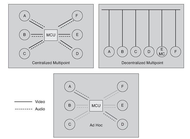
H.323 defines three types of multipoint conferences, as shown in Figure 5-11: centralized, decentralized (or sometimes called distributed), and ad hoc. H.323 also defines a hybrid of the first two.
All types of multipoint conferences rely on a single MC to coordinate the membership of a conference. Each endpoint has an H.245 control channel connection to the MC. Either the MC or the endpoint initiates the control channel setup. H.323 defines the following three types of conferences:
■ Centralized multipoint conference: The endpoints must have their audio, video, or data channels connected to a multipoint processor (MP). The MP performs mixing and switching of the audio, video, and data, and if the MP supports the capability, each endpoint can operate in a different mode.
Figure 5-11 Multipoint Conferences
■ Distributed multipoint conference: The endpoints do not have a connection to an MP. Instead, endpoints multicast their audio, video, and data streams to all participants in the conference. Because an MP is not available for switching and mixing, any mixing of the conference streams is a function of the endpoint, and all endpoints must use the same communication parameters.
To accommodate situations in which two streams (audio and video) would be handled by the different multipoint conference models, H.323 defines a "hybrid." A hybrid describes a situation in which the audio and video streams are managed by a single H.245 control channel with the MC, but where one stream relies on multicast (according to the distributed model) and the other uses the MP (as in the centralized model).
■ Ad hoc multipoint conference: Any two endpoints in a call can convert their relationship into a point-to-point conference. If neither of the endpoints has a collocated MC, the services of a gatekeeper are used. When the point-to-point conference is created, other endpoints become part of the conference by accepting an invitation from a current participant, or the endpoint can request to join the conference.
Configuring H.323 Gateways
Options for setting up an H.323 gateway include the following:
■ Enable H.323 VoIP call services (required)
■ Configure an interface as an H.323 gateway interface (required)
■ Configure codecs (optional)
■ Configure Dual Tone Multifrequency (DTMF) and fax relay (optional)
■ Adjust H.225 settings (optional)
Depending on the deployment scenario, you might be configuring only the required features or many of the options available for an H.323 voice gateway.
H.323 Configuration Example
Figure 5-12 offers a sample topology that needs to be configured for H.323.
Figure 5-12 H.323 Configuration Example Topology
As a network administrator, you have been asked to deploy an H.323-based VoIP network between two corporate sites. Both sites are using a Cisco IOS H.323 capable gateway for the remote connection. You should deploy the network to meet network requirements:
■ Use H.323 as a signaling protocol.
■ The H.323 ID of the gateway should be gw1.
■ A loopback interface is to be used as the connection to the remote site.
■ Multiple codecs must be available for negotiation in this order:
■ G.711
■ G.729
■ E.164-Address Registration must be configured, because some phones are directly connected to the gateway.
■ H.323 timers need to be tuned.
A four-step procedure can then be followed to configure an H.323 gateway according to network requirements:
Step 1. Enable H.323 VoIP services globally. Step 2. Configure an interface as an H.323 gateway.
Step 3. Create a codec voice class and populate with a list of codecs in order of their preference.
Step 4. Adjust H.225 timers.
These four steps are detailed as follows:
Step 1. Enable H.323 VoIP services globally.
Enter voice-service configuration mode and specify a voice-encapsulation type.
The following is a description of the syntax:
■ pots: Plain Old Telephone Service (POTS) voice service
■ voatm: Voice over ATM (VoATM) encapsulation
■ vofr: Voice over Frame Relay (VoFR) encapsulation
■ voip: Voice over IP (VoIP) encapsulation
Voice-service configuration mode is used for packet telephony service commands that affect the gateway globally.
Select H.323-call-processing submode and enable the H.323 voice service configuration commands.
Activate the service. Router(conf-voi-serv)#no shutdown
Step 2. Configure an interface as an H.323 gateway.
Enter interface configuration mode for the interface that is connected to the gatekeeper.
Assign an IP address to the interface.
Identify the interface as a VoIP gateway interface.
Define the H.323 name of the gateway.
Designate a source IP address for the voice gateway.
This command sets the source IP address to be used for this gateway. The IP address is used for outgoing H.323 traffic, which includes H.225, H.245, and RAS messages. You do not have to issue this command on the interface that you defined as the voice gateway interface (although it might be more convenient to do so). Use this command on the interface that contains the IP address to which you want to bind (for example, a loopback interface).


![tmp1D-98_thumb[2][2] tmp1D-98_thumb[2][2]](http://what-when-how.com/wp-content/uploads/2012/03/tmp1D98_thumb22_thumb.png)
