This section explains the protocols and processes involved in delivering VoIP packets as opposed to delivering digitized voice over circuit-switched networks. It also explains the RTP as the transport protocol of choice for voice and discusses the benefits of RTP header compression (cRTP).
End-to-End Delivery of Voice
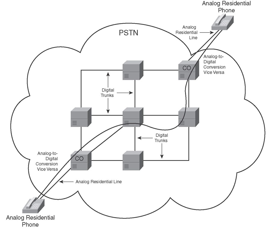
To review the traditional model of voice communication over the PSTN, imagine a residential phone that connects to the telco CO switch using an analog telephone line. After the phone goes off-hook and digits are dialed and sent to the CO switch, the CO switch, using a special signaling protocol, finds and sends call setup signaling messages to the CO that connects to the line of the destination number. The switches within the PSTN are connected using digital trunks such as T1/E1 or T3/E3. If the call is successful, a single channel (DS0) from each of the trunks on the path that connects the CO switches of the caller and called number is dedicated to this phone call. Figure 1-10 shows a path from the calling party CO switch on the left to the called party CO switch on the right.
Figure 1-10 Voice Call over Traditional Circuit-Switched PSTN
After the path between the CO switches at each end is set up, while the call is active, analog voice signals received from the analog lines must be converted to digital format, such as G.711 PCM, and transmitted over the DS0 that is dedicated to this call. The digital signal received at each CO must be converted back to analog before it is transmitted over the residential line. The bit transmission over DS0 is a synchronous transmission with guaranteed bandwidth, low and constant end-to-end delay, plus no chance for reordering. When the call is complete, all resources and the DS0 channel that is dedicated to this call are released and are available to another call.
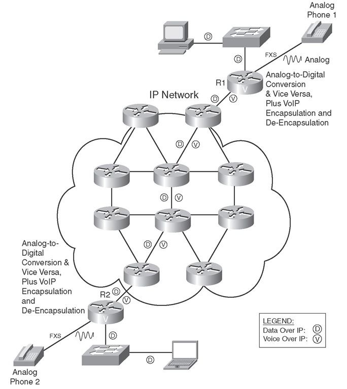
If two analog phones were to make a phone call over an IP network, they would each need to be plugged into the FXS interface of a voice gateway. Figure 1-11 displays two such gateways (R1 and R2) connected over an IP network, each of which has an analog phone connected to its FXS interface.
Figure 1-11 Voice Call over IP Networks
Assume that phone 1 on R1 goes off-hook and dials a number that R1 maps to R2. R1 will send a VoIP signaling call setup message to R2. If the call is accepted and it is set up, each of R1 and R2 will have to do the following:
■ Convert the analog signal received from the phone on the FXS interface to digital (using a codec such as G.711).
■ Encapsulate the digital voice signal into IP packets.
■ Route the IP packets toward the other router.
■ De-encapsulate the digital voice from the received IP packets.
■ Convert the digital voice to analog and transmit it out of the FXS interface.
Notice that in this case, in contrast to a call made over the circuit-switched PSTN network, no end-to-end dedicated path is built for the call. IP packets that encapsulate digitized voice (20 ms of audio by default) are sent independently over the IP network and might arrive out of order and experience different amounts of delay. (This is called jitter.) Because voice and data share the IP network with no link or circuit dedicated to a specific flow or call, the number of data and voice calls that can be active at each instance varies. Also, it affects the amount of congestion, loss, and delay in the network.
Protocols Used in Voice Encapsulation
Even though the term VoIP implies that digitized voice is encapsulated in IP packets, other protocol headers and mechanisms are involved in this process. Although the two major TCP/IP transport layer protocols, namely TCP and UDP, have their own merits, neither of these protocols alone is a suitable transport protocol for real-time voice. RTP, which runs over UDP using UDP ports 16384 through 32767, offers a good transport layer solution for real-time voice and video. Table 1-5 compares TCP, UDP, and RTP protocols with respect to reliability, sequence numbering (re-ordering), time-stamping, and multiplexing.
Table 1-5 Comparing Suitability of TCP/IP Transport Protocols for Voice
|
Feature |
Required for Voice |
TCP Offers |
UDP Offers |
RTP Offers |
|
Reliability |
No |
Yes |
No |
No |
|
Sequence numbering and reordering |
Yes |
Yes |
No |
Yes |
|
Time-stamping |
Yes |
No |
No |
Yes |
|
Multiplexing |
Yes |
Yes |
Yes |
No |
TCP provides reliability by putting sequence numbers on the TCP segments sent and expecting acknowledgements for the TCP segment numbers arriving at the receiver device. If a TCP segment is not acknowledged before a retransmission timer expires, the TCP segment is resent. This model is not suitable for real-time applications such as voice, because the resent voice arrives too late for it to be useful. Therefore, reliability is not a necessary feature for a voice transport protocol. UDP and RTP do not offer reliable transport. Please note, however, that if the infrastructure capacity, configuration, and behavior are such that there are too many delayed or lost packets, the quality of voice and other real-time applications will deteriorate and become unacceptable.
Data segmentation, sequence numbering, reordering, and reassembly of data are services that the transport protocol must offer, if the application does not or cannot perform those tasks. The protocol to transport voice must offer these services. TCP and RTP offer those services, but pure UDP does not.
Voice or audio signal is released at a certain rate from its source. The receiver of the voice or audio signal must receive it at the same rate that the source has released it; otherwise, it will sound different or annoying, or it might even become incomprehensible. Putting timestamps on the segments encapsulating voice, at source, enables the receiving end to release the voice at the same rate that it was released at the source. RTP adds timestamps in the segments at source, but TCP and UDP do not.
Both TCP and UDP allow multiple applications to simultaneously use their services to transport application data, even if all the active flows and sessions originate and terminate on the same pair of IP devices. The data from different applications is distinguished based on the TCP or UDP port number that is assigned to the application while it is active. This capability of the TCP and UDP protocols is called multiplexing. On the other hand, RTP flows are differentiated based on the unique UDP port number that is assigned to each of the RTP flows. UDP numbers 16384 through 32767 are reserved for RTP. RTP does not have a multiplexing capability.
Knowing that RTP runs over UDP, considering the fact that neither UDP nor RTP offers the unneeded reliability and overhead offered by TCP, and that RTP uses sequence numbers and time-stamping, you can conclude that RTP is the best transport protocol for voice, video, and other realtime applications. Please note that even though the reliability that TCP offers might not be useful for voice applications, it is desirable for certain other applications.
RTP runs over UDP; therefore, a VoIP packet has IP (20 bytes), UDP (8 bytes), and RTP (12 bytes) headers added to the encapsulated voice payload. DSPs usually make a package out of 10-ms worth of analog voice, and two of those packages are usually transported within one IP packet. (A total of 20-ms worth of voice in one IP packet is common.) The number of bytes resulting from 20 ms (2 x 10 ms) worth of analog voice directly depends on the codec used. For instance, G.711, which generates 64 Kbps, produces 160 bytes from 20 ms of analog voice, whereas G.729, which generates 8 Kbps, produces 20 bytes for 20 ms of analog voice signal. The RTP, UDP, and IP headers, which total 40 bytes, are added to the voice bytes (160 bytes for G.711 and 20 bytes for G.729) before the whole group is encapsulated in the Layer 2 frame and transmitted.
Figure 1-12 displays two VoIP packets. One packet is the result of the G.711 codec, and the other is the result of the G.729 codec. Both have the RTP, UDP, and IP headers. The Layer 2 header is not considered here. The total number of bytes resulting from IP, UDP, and RTP is 40. Compare this 40-byte overhead to the size of the G.711 payload (160 bytes) and of the G.729 payload (20 bytes). The ratio of overhead to payload is 40/160, or 25 percent, when G.711 is used; however, the overhead-to-payload ratio is 40/20, or 200 percent, when G.729 is used!
Figure 1-12 Voice Encapsulation Utilizing G.711 and G.729
If you ignore the Layer 2 overhead for a moment, just based on the overhead imposed by RTP, UDP, and IP, you can recognize that the required bandwidth is more than the bandwidth that is needed for the voice payload. For instance, when the G.711 codec is used, the required bandwidth for voice only is 64 Kbps, but with 25 percent added overhead of IP, UDP, and RTP, the required bandwidth increases to 80 Kbps. If G.729 is used, the bandwidth required for pure voice is only 8 Kbps, but with the added 200 percent overhead imposed by IP, UDP, and RTP, the required bandwidth jumps to 24 Kbps. Again, note that the overhead imposed by the Layer 2 protocol and any other technologies such as tunneling or security has not even been considered.
Reducing Header Overhead
An effective way of reducing the overhead imposed by IP, UDP, and RTP is Compressed RTP (cRTP). cRTP is also called RTP header compression. Even though its name implies that cRTP compresses the RTP header only, the cRTP technique actually significantly reduces the overhead imposed by all IP, UDP, and RTP protocol headers. cRTP must be applied on both sides of a link, and essentially the sender and receiver agree to a hash (number) that is associated with the 40 bytes of IP, UDP, and TCP headers. Note that cRTP is applied on a link-by-link basis.
The premise of cRTP is that most of the fields in the IP, UDP, and RTP headers do not change among the elements (packets) of a common packet flow. After the initial packet with all the headers is submitted, the following packets that are part of the same packet flow do not carry the 40 bytes of headers. Instead, the packets carry the hash number that is associated with those 40 bytes (sequence number is built in the hash). The main difference among the headers of a packet flow is the header checksum (UDP checksum). If cRTP does not use this checksum, the size of the overhead is reduced from 40 bytes to only 2 bytes. If the checksum is used, the 40 bytes overhead is reduced to 4 bytes. If, during transmission of packets, a cRTP sender notices that a packet header has changed from the normal pattern, the entire header instead of the hash is submitted.
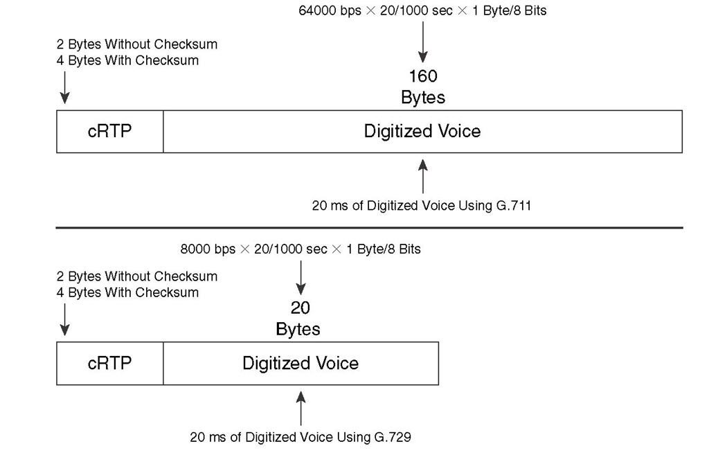
Figure 1-13 displays two packets. The top packet has a 160-byte voice payload because of usage of the G.711 codec, and a 2-byte cRTP header (without checksum). The cRTP overhead-to-voice payload ratio in this case is 2/160, or 1.25 percent. Ignoring Layer 2 header overhead, because G.711 requires 64 Kbps for the voice payload, the bandwidth needed for voice and the cRTP overhead together would be 64.8 Kbps (without header checksum). The bottom packet has a 20-byte voice payload because of usage of the G.729 codec and a 2-byte cRTP header (without checksum). The cRTP overhead-to-voice payload ratio in this case is 2/20, or 10 percent. Ignoring Layer 2 header overhead, because G.729 requires 8 Kbps for the voice payload, the bandwidth needed for voice and the cRTP overhead together would be 8.8 Kbps (without header checksum).
Figure 1-13 RTP Header Compression (cRTP)
The benefit of using cRTP with smaller payloads (such as digitized voice) is more noticeable than it is for large payloads. Notice that with cRTP, the total bandwidth requirement (without Layer 2 overhead considered) dropped from 80 Kbps to 64.8 Kbps for G.711, and it dropped from 24 Kbps to 8.8 Kbps for G.729. The relative gain is more noticeable for G.729. You must, however, consider factors before enabling cRTP on a link:
■ cRTP does offer bandwidth saving, but it is only recommended for use on slow links (links with less than 2 Mbps bandwidth). More accurately, Cisco recommends cRTP on 2 Mbps links only if the cRTP is performed in hardware. cRTP is only recommended on the main processor if the link speed is below 768 kbps.
■ cRTP has a processing overhead, so make sure the device where you enable cRTP has enough resources.
■ The cRTP process introduces a delay due to the extra computations and header replacements.
■ You can limit the number of cRTP sessions on a link. By default, Cisco IOS allows up to only 16 concurrent cRTP sessions. If enough resources are available on a device, you can increase this value.


