Upon completion of this section, you will be able to identify the steps involved in converting an analog voice signal to a digital voice signal, explain the Nyquist theorem, the reason for taking 8000 voice samples per second; and explain the method for quantization of voice samples. Furthermore, you will be familiar with standard voice compression algorithms, their bandwidth requirements, and the quality of the results they yield. Knowing the purpose of DSP in voice gateways is the last objective of this section.
Basic Voice Encoding: Converting Analog to Digital
Converting analog voice signal to digital format and transmitting it over digital facilities (such as T1/E1) had been created and put into use before Bell (a North American telco) invented VoIP technology in 1950s. If you use digital PBX phones in your office, you must realize that one of the first actions that these phones perform is converting the analog voice signal to a digital format. When you use your regular analog phone at home, the phone sends analog voice signal to the telco CO. The Telco CO converts the analog voice signal to digital format and transmits it over the public switched telephone network (PSTN). If you connect an analog phone to the FXS interface of a router, the phone sends an analog voice signal to the router, and the router converts the analog signal to a digital format. Voice interface cards (VIC) require DSPs, which convert analog voice signals to digital signals, and vice versa.
Analog-to-digital conversion involves four major steps:
1. Sampling
2. Quantization
3. Encoding
4. Compression (optional)
Sampling is the process of periodic capturing and recording of voice. The result of sampling is called a pulse amplitude modulation (PAM) signal. Quantization is the process of assigning numeric values to the amplitude (height or voltage) of each of the samples on the PAM signal using a scaling methodology. Encoding is the process of representing the quantization result for each PAM sample in binary format. For example, each sample can be expressed using an 8-bit binary number, which can have 256 possible values.
One common method of converting analog voice signal to digital voice signal is pulse code modulation (PCM), which is based on taking 8000 samples per second and encoding each sample with an 8-bit binary number. PCM, therefore, generates 64,000 bits per second (64 Kbps); it does not perform compression. Each basic digital channel that is dedicated to transmitting a voice call within PSTN (DS0) has a 64-kbps capacity, which is ideal for transmitting a PCM signal.
Compression, the last step in converting an analog voice signal to digital, is optional. The purpose of compression is to reduce the number of bits (digitized voice) that must be transmitted per second with the least possible amount of voice-quality degradation. Depending on the compression standard used, the number of bits per second that is produced after the compression algorithm is applied varies, but it is definitely less than 64 Kbps.
Basic Voice Encoding: Converting Digital to Analog
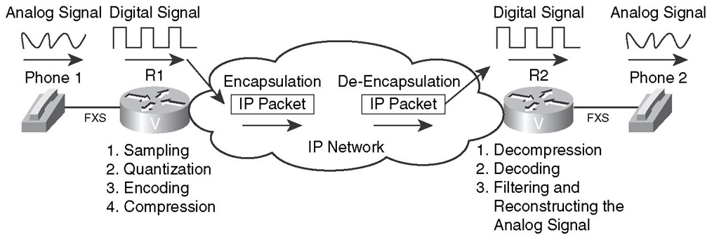
When a switch or router that has an analog device such as a telephone, fax, or modem connected to it receives a digital voice signal, it must convert the analog signal to digital or VoIP before transmitting it to the other device. Figure 1-5 shows that router R1 receives an analog signal and converts it to digital, encapsulates the digital voice signal in IP packets, and sends the packets to router R2. On R2, the digital voice signal must be de-encapsulated from the received packets. Next, the switch or router must convert the digital voice signal back to analog voice signal and send it out of the FXS port where the phone is connected.
Figure 1-5 Converting Analog Signal to Digital and Digital Signal to Analog
Converting digital signal back to analog signal involves the following steps:
1. Decompression (optional)
2. Decoding and filtering
3. Reconstructing the analog signal
If the digitally transmitted voice signal was compressed at the source, at the receiving end, the signal must first be decompressed. After decompression, the received binary expressions are decoded back to numbers, which regenerate the PAM signal. Finally, a filtering mechanism attempts to remove some of the noise that the digitization and compression might have introduced and regenerates an analog signal from the PAM signal. The regenerated analog signal is hopefully very similar to the analog signal that the speaker at the sending end had produced. Do not forget that DPS perform digital-to-analog conversion, similar to analog to digital conversion.
The Nyquist Theorem
The number of samples taken per second during the sampling stage, also called the sampling rate, has a significant impact on the quality of digitized signal. The higher the sampling rate is, the better quality it yields; however, a higher sampling rate also generates higher bits per second that must be transmitted. Based on the Nyquist theorem, a signal that is sampled at a rate at least twice the highest frequency of that signal yields enough samples for accurate reconstruction of the signal at the receiving end.
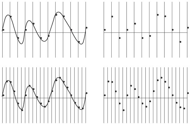
Figure 1-6 shows the same analog signal on the left side (top and bottom) but with two sampling rates applied: the bottom sampling rate is twice as much as the top sampling rate. On the right side of Figure 1-6, the samples received must be used to reconstruct the original analog signal. As you can see, with twice as many samples received on the bottom-right side as those received on the top-right side, a more accurate reconstruction of the original analog signal is possible.
Human speech has a frequency range of 200 to 9000 Hz. Hz stands for Hertz, which specifies the number of cycles per second in a waveform signal. The human ear can sense sounds within a frequency range of 20 to 20,000 Hz. Telephone lines were designed to transmit analog signals within the frequency range of 300 to 3400 Hz. The top and bottom frequency levels produced by a human speaker cannot be transmitted over a phone line. However, the frequencies that are transmitted allow the human on the receiving end to recognize the speaker and sense his/her tone of voice and inflection. Nyquist proposed that the sampling rate must be twice as much as the highest frequency of the signal to be digitized. At 4000 Hz, which is higher than 3400 Hz (the maximum frequency that a phone line was designed to transmit), based on the Nyquist theorem, the required sampling rate is 8000 samples per second.
Figure 1-6 Effect of Higher Sampling Rate
Quantization
Quantization is the process of assigning numeric values to the amplitude (height or voltage) of each of the samples on the PAM signal using a scaling methodology. A common scaling method is made of eight major divisions called segments on each polarity (positive and negative) side. Each segment is subdivided into 16 steps. As a result, 256 discrete steps (2 x 8 x 16) are possible.
The 256 steps in the quantization scale are encoded using 8-bit binary numbers. From the 8 bits, 1 bit represents polarity (+ or -), 3 represent segment number (1 through 8), and 4 bits represent the step number within the segment (1 through 16). At a sampling rate of 8000 samples per second, if each sample is represented using an 8-bit binary number, 64,000 bits per second are generated for an analog voice signal. It must now be clear to you why traditional circuit-switched telephone networks dedicated 64 Kbps channels, also called DS0s (Digital Signal Level 0), to each telephone call.
Because the samples from PAM do not always match one of the discrete values defined by quantization scaling, the process of sampling and quantization involves some rounding. This rounding creates a difference between the original signal and the signal that will ultimately be reproduced at the receiver end; this difference is called quantization error. Quantization error or quantization noise, is one of the sources of noise or distortion imposed on digitally transmitted voice signals.
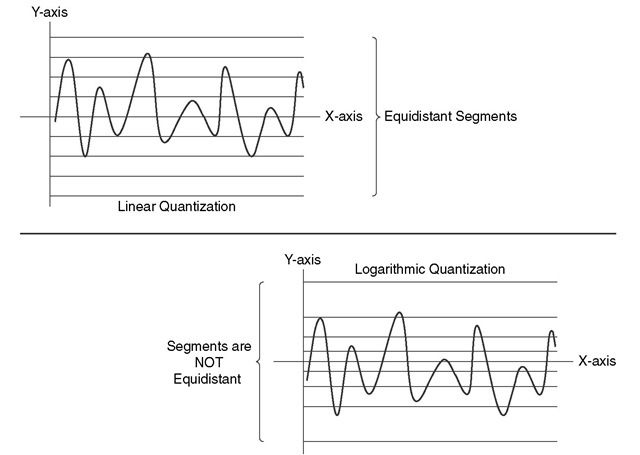
Figure 1-7 shows two scaling models for quantization. If you look at the graph on the top, you will notice that the spaces between the segments of that graph are equal. However, the spaces between the segments on the bottom graph are not equal: the segments closer to the x-axis are closer to each other than the segments that are further away from the x-axis. Linear quantization uses graphs with segments evenly spread, whereas logarithmic quantization uses graphs that have unevenly spread segments. Logarithmic quantization yields smaller signal-to-noise quantization ratio (SQR), because it encounters less rounding (quantization) error on the samples (frequencies) that human ears are more sensitive to (very high and very low frequencies).
Figure 1-7 Linear Quantization and Logarithmic Quantization
Two variations of logarithmic quantization exist: A-Law and u-Law. Bell developed u-Law (pronounced me-you-law) and it is the method that is most common in North America and Japan. ITU modified u-Law and introduced A-Law, which is common in countries outside North America (except Japan). When signals have to be exchanged between a u-Law country and an A-Law country in the PSTN, the u-Law country must change its signaling to accommodate the A-Law country.
Compression Bandwidth Requirements and Their Comparative Qualities
Several ITU compression standards exist. Voice compression standards (algorithms) differ based on the following factors:
■ Bandwidth requirement
■ Quality degradation they cause
■ Delay they introduce
■ CPU overhead due to their complexity
Several techniques have been invented for measuring the quality of the voice signal that has been processed by different compression algorithms (codecs). One of the standard techniques for measuring quality of voice codecs, which is also an ITU standard, is called mean opinion score (MOS). MOS values, which are subjective and expressed by humans, range from 1 (worst) to 5 (perfect or equivalent to direct conversation). Table 1-3 displays some of the ITU standard codecs and their corresponding bandwidth requirements and MOS values.
Table 1-3 Codec Bandwidth Requirements and MOS Values
|
Codec Standard |
Associated Acronym |
Codec Name |
Bit Rate (BW) |
Quality Based on MOS |
|
G.711 |
PCM |
Pulse Code Modulation |
64 Kbps |
4.10 |
|
G.726 |
ADPCM |
Adaptive Differential PCM |
32, 24, 16 Kbps |
3.85 (for 32 Kbps) |
|
G.728 |
LDCELP |
Low Delay Code Exited Linear Prediction |
16 Kbps |
3.61 |
|
G.729 |
CS-ACELP |
Conjugate Structure Algebraic CELP |
8 Kbps |
3.92 |
|
G.729A |
CS-ACELP Annex a |
Conjugate Structure Algebraic CELP Annex A |
8 Kbps |
3.90 |
MOS is an ITU standard method of measuring voice quality based on the judgment of several participants; therefore, it is a subjective method. Table 1-4 displays each of the MOS ratings along with its corresponding interpretation, and a description for its distortion level. It is noteworthy that an MOS of 4.0 is deemed to be Toll Quality.
Table 1-4 Mean Opinion Score
|
Rating |
Speech Quality |
Level of Distortion |
|
5 |
Excellent |
Imperceptible |
|
4 |
Good |
Just perceptible but not annoying |
|
3 |
Fair |
Perceptible but slightly annoying |
|
2 |
Poor |
Annoying but not objectionable |
|
1 |
Unsatisfactory |
Very annoying and objectionable |
Perceptual speech quality measurement (PSQM), ITU’s P.861 standard, is another voice quality measurement technique implemented in test equipment systems offered by many vendors. PSQM is based on comparing the original input voice signal at the sending end to the transmitted voice signal at the receiving end and rating the quality of the codec using a 0 through 6.5 scale, where 0 is the best and 6.5 is the worst.
Perceptual analysis measurement system (PAMS) was developed in the late 1990s by British Telecom. PAMS is a predictive voice quality measurement system. In other words, it can predict subjective speech quality measurement methods such as MOS.
Perceptual evaluation of speech quality (PESQ), the ITU P.862 standard, is based on work done by KPN Research in the Netherlands and British Telecommunications (developers of PAMS). PESQ combines PSQM and PAMS. It is an objective measuring system that predicts the results of subjective measurement systems such as MOS. Various vendors offer PESQ-based test equipment.
Digital Signal Processors
Voice-enabled devices such as voice gateways have special processors called DSPs. DSPs are usually on packet voice DSP modules (PVDM). Certain voice-enabled devices such as voice network modules (VNM) have special slots for plugging PVDMs into them. Figure 1-8 shows a network module high density voice (NM-HDV) that has five slots for PVDMs. The NM in Figure 1-8 has four PVDMs plugged into it . Different types of PVDMs have different numbers of DSPs, and each DSP handles a certain number of voice terminations. For example, one type of DSP can handle tasks such as codec and transcoding for up to 16 voice channels if a low-complexity codec is used, or up to 8 voice channels if a high-complexity codec is used.
Figure 1-8 Network Module with PVDMs
DSPs provide three major services:
■ Voice termination
■ Transcoding
■ Conferencing
Calls to or from voice interfaces of a voice gateway are terminated by DSPs. DSP performs analog-to-digital and digital-to-analog signal conversion. It also performs compression (codec), echo cancellation, voice activity detection (VAD), comfort noise generation (CNG), jitter handling, and some other functions.
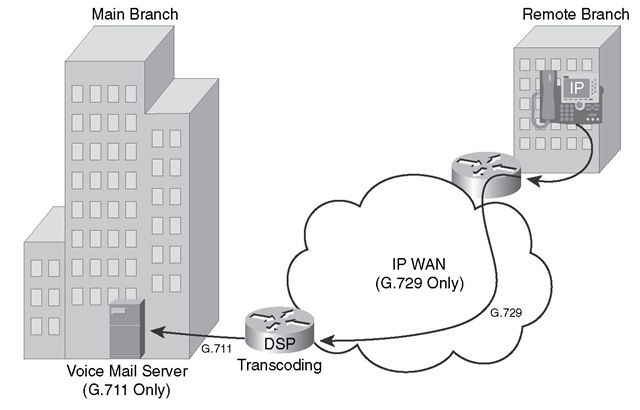
When the two parties in an audio call use different codecs, a DSP resource is needed to perform codec conversion; this is called transcoding. Figure 1-9 shows a company with a main branch and a remote branch with an IP connection over WAN. The voice mail system is in the main branch, and it uses the G.711 codec. However, the branch devices are configured to use G.729 for VoIP communication with the main branch. In this case, the edge voice router at the main branch needs to perform transcoding using its DSP resources so that the people in the remote branch can retrieve their voice mail from the voice mail system at the main branch.
DSPs can act as a conference bridge: they can receive voice (audio) streams from the participants of a conference, mix the streams, and send the mix back to the conference participants. If all the conference participants use the same codec, it is called a single-mode conference, and the DSP does not have to perform codec translation (called transcoding). If conference participants use different codecs, the conference is called a mixed-mode conference, and the DSP must perform transcoding. Because mixed-mode conferences are more complex, the number of simultaneous mixed-mode conferences that a DSP can handle is less than the number of simultaneous single-mode conferences it can support.
Figure 1-9 DSP Transcoding Example


