Wireless RF is an OSI Layer 2 technology, and its QoS is currently based on 802.11e or WMM specifications. With the addition of WLANs, to maintain end-to-end QoS in a network, it is necessary to perform mapping between Layer 2 (802.1p) priority or Layer 3 DSCP (or IP precedence) and 802.11e priority (or WMM access category). If a wireless AP connects to an access port (non-trunk port, lacking 801.1p marking) of a LAN switch, the Layer 2 802.11e (or WMM) marking of data coming from the wireless client is lost because the data is forwarded from the AP to the LAN switch. This is also true for the traffic arriving at the LAN switch (with Layer 2 801.1p marking), which then has to forward the traffic through an access port to the wireless AP. In the absence of Layer 2 QoS information, such as on a non-trunk connection, it will be necessary to utilize the Layer 3 QoS information such as the DSCP marking.
In the Cisco centralized LWAP wireless architecture (with Split-MAC architecture as its core), WLAN controller ensures that traffic traversing between it and the LWAP maintains its QoS information. The WLAN data coming from the wireless clients to the LWAP is tunneled to the WLAN controller using Lightweight Access Point Protocol (LWAPP). In the opposite direction, the traffic coming from the wired LAN to the WLAN controller is also tunneled to the LWAP using LWAPP.
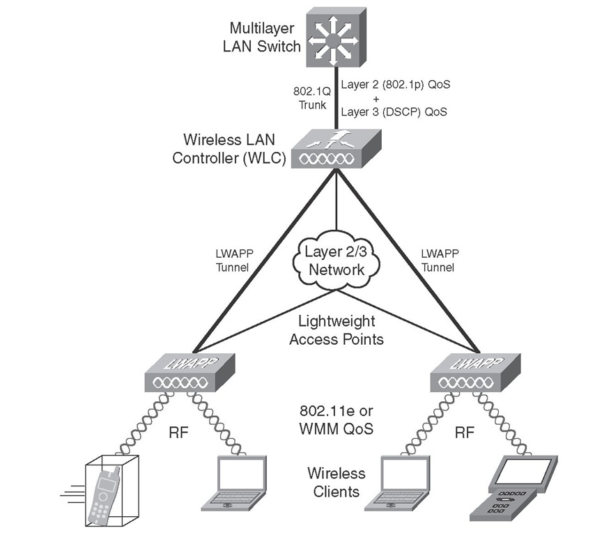
Figure 8-2 shows a WLAN controller with a wired 802.1Q trunk connection to a multilayer LAN switch. The WLAN controller has two LWAPs associated to it. The WLAN controller has an LWAPP tunnel set up with each of the LWAPs. The LWAPP tunnel can be set up over a Layer 2 or a Layer 3 network. In Layer 2 mode, the LWAPP data unit is in an Ethernet frame. Furthermore, the WLAN controller and the AP must be in the same broadcast domain and IP subnet. In Layer 3 mode, however, the 3 LWAPP data unit is in a User Datagram Protocol (UDP/IP frame). Moreover, the WLAN controller and AP can be in the same or different broadcast domains and IP subnets. Examples for the supported wireless LAN controllers are Cisco 2000, 4100, 4400 Series wireless LAN controllers, Cisco WiSM, Cisco WLCM for integrated services routers, Airespace 3500, 4000, and 4100 Series wireless LAN controllers. Examples for the supported APs are Cisco Aironet 1000, 1130, 1230, 1240, and 1500 series LWAPs.
Figure 8-2 LWAPP Tunnel in the Split-MAC Architecture
To maintain continuous (end-to-end) QoS, the WLAN controller on one end of the LWAPP tunnel and the LWAP at the other end of the LWAPP tunnel must do some mapping between the QoS marking of the received data units and the QoS markings/fields of the data unit they send forward. The wireless LAN controller sends and receives 802.1Q frames to and from the wired multilayer LAN switch. 802.1Q frames have the CoS (priority/802.1p) field for QoS marking purposes. The wireless LAN controller and the LWAP send and receive LWAPP data units to each other. The LWAPP data unit has an 802.1p (CoS) equivalent field and a DSCP equivalent field. (The LWAP does not understand the 802.1p field of the LWAPP data unit.) The LWAP and the wireless clients exchange RF, with 802.11e (or WMM) providing the QoS marking field. Table 8-4 shows the mapping between IP DSCP value and 802.1p and 802.11e values.
Table 8-4 QoS Markings Mapping Table
|
Cisco 802.1Q/P Priority-Based Traffic Type |
IP DSCP |
802.1p Priority |
802.11e Priority |
|
Network control/reserved |
56-62 |
7 |
7 |
|
Inter-network control/IP routing |
48 |
6 |
7 |
|
Voice |
46 (EF) |
5 |
6 |
|
Video |
34 (AF41) |
4 |
5 |
|
Voice control |
26 (AF31) |
3 |
4 |
|
Background (Gold) |
18 (AF21) |
2 |
2 |
|
Background (Silver) |
10 (AF11) |
1 |
1 |
|
Best effort |
0 (BE) |
0 |
0 or 3 |
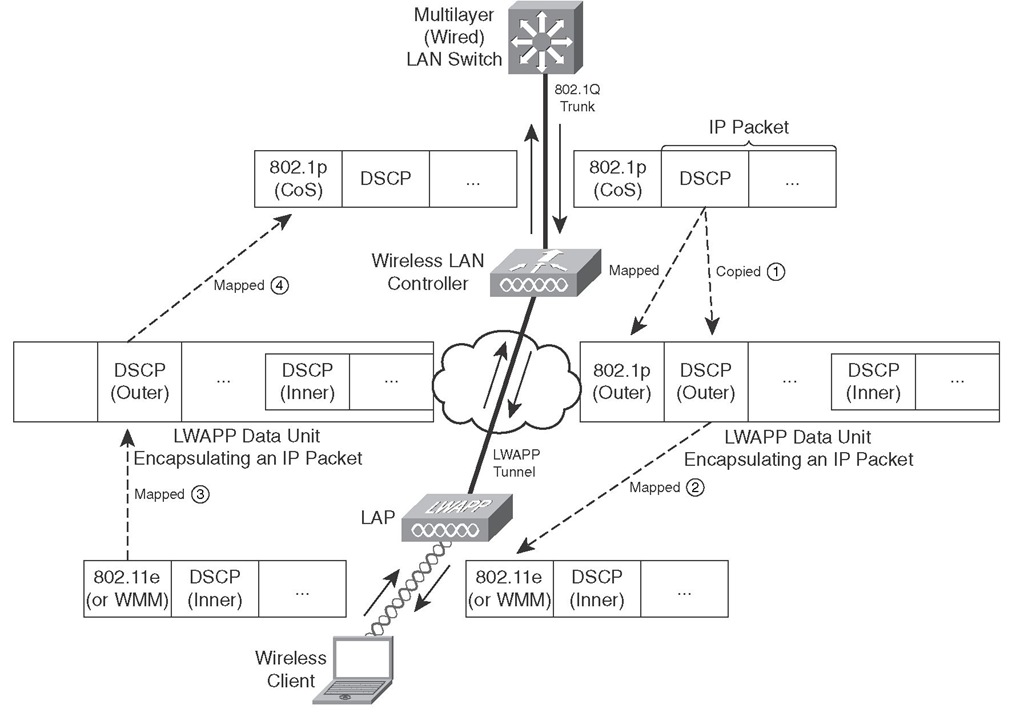
Figure 8-3 is a comprehensive depiction of data moving from a multilayer LAN switch to a wireless client through a wireless LAN controller and an LWAP, and data moving in the opposite direction from the wireless client to the multilayer LAN switch through an LWAP and a wireless LAN controller. This process involves four steps, accordingly marked in Figure 8-3, which will be addressed next.
Step 1 in Figure 8-3 shows that when the WLAN controller receives an 802.1Q frame (encapsulating an IP packet) from the multilayer LAN switch, it forwards the IP packet toward the LWAP, encapsulating it in an LWAPP data unit. For QoS continuity purposes, the WLAN controller copies the IP DSCP field (inner) to the LWAPP data unit DSCP field (outer). The WLAN controller also maps the IP DSCP field (inner) to the LWAPP data unit’s 802.1p field (outer). The mapping of DSCP to 802.1p is done according to Table 8-4. Please note that the LWAPP control packets exchanged between the WLAN controller and the LWAP are always tagged with the 802.1p value of 7. Indeed, LWAPP reserves the 802.1p value of 7 for the LWAPP control packets.
Step 2 in Figure 8-3 shows that when the LWAP receives a LWAPP data unit (encapsulating an IP packet) from the WLAN controller, it forwards the IP packet toward the wireless client using RF, and it uses 802.11e/WMM for Layer 2 QoS marking. The LAWP maps the DSCP field from the LWAPP data unit to the 802.11e/WMM field based on Table 8-4.
Figure 8-3 Mapping of Inner QoS Fields to LWAPP Tunnel QoS Fields
In Step 3, shown in Figure 8-3, the LWAP receives RF from the wireless client transporting an IP packet with the Layer 2 QoS marking in the 802.11e/WMM field. The LWAP forwards the IP packet toward the WLAN controller, encapsulating it in an LWAPP data unit. For QoS continuity purposes, the LWAP maps the 802.11e value to the DSCP field on the LWAPP data unit based on Table 8-4. Note that because the LWAP does not understand 802.1p, it does not mark that field on the LWAPP data unit.
Finally, in Step 4, shown in Figure 8-3, the WLAN controller receives an LWAPP data unit from the LWAP encapsulating an IP packet. The WLAN controller forwards the IP packet toward the multilayer LAN switch, encapsulating it in an 801.1Q frame (over the trunk connection). For QoS continuity purposes, the WLAN controller maps the DSCP field from the LWAPP data unit to the 802.1p field on the 802.1Q frame based on Table 8-4. Please note that packets with no QoS markings received from the WLAN will be categorized as best-effort (default Silver) when the WLAN controller transmits them toward the LAN.


