Geoscience Reference
In-Depth Information
2. Stand at a known location and take a bearing on a feature
identifi ed on a map of the area (Section 2.3.3 explains how
to do this).
3. Compare the compass reading with the azimuth between
your location and the feature provided by the map; the
difference is magnetic declination.
4. Alternatively use a straight feature on the map such as a
wall or forest boundary and compare the reading from
sighting along the linear feature with that given on the map.
2
Once you have determined the declination ensure that you
adjust the declination in the correct direction. On the Silva-
type compass the numbers increase in a clockwise direction
whereas they increase in an anticlockwise direction on the
Brunton-type. This is because of the different way in which the
dial works; when used correctly they will give exactly the same
azimuth reading.
2.3.1 Orientation of a dipping plane
The most common type of measurement in geology is the
orientation of a dipping plane: for instance a bedding plane, a
cleavage plane or a fault plane. The following three parameters
need to be measured and recorded: (1) maximum angle at
which the plane dips (dip magnitude) in degrees relative to the
horizontal; (2) the orientation of the plane relative to north
(strike, i.e. orientation of the
horizontal
line defi ned by the
plane) in degrees; and (3) the general dip direction (Figure 2.5)
because from the strike alone the plane could be dipping in
one of two directions at 180° to each other. To prevent
confusion, strike is always recorded as a three-digit number
and dip as a two-digit number. Apart from this convention on
the number of digits, there are several equally valid and
commonly used notations to combine the dip and strike; these
are summarized later in Table 8.1. For clarity, a consistent style
of notation should be chosen.
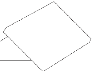
dipping
plane
N
strike
dip direction
dip magnitude
Figure 2.5
Sketch to show
strike, dip magnitude and dip
direction of a plane. See also
Figures 2.6 and 2.7. Using the
north arrow shown this imaginary
plane is striking east-west (270° or
090°) and dipping to the north.
Any direction down the dipping
plane that is not at right angles to
the strike will be an apparent dip
direction and will have a smaller
dip magnitude than the true dip
magnitude.
Determination of the orientation of a dipping plane by
the contact method
The orientation of a dipping plane is most commonly measured
using the contact method. This is illustrated for the Silva-type
compass-clinometer in Figure 2.6 (pp.
12-13) and the Brunton-
type compass-clinometer in Figure 2.7 (pp.
14-15). The exact
order that you complete the steps and obtain the strike and dip
of the plane is not crucial; this will depend on the instrument
used, fi eld conditions and personal preference. What is important
is ensuring that you record the three pieces of information
(strike, dip magnitude and dip direction). Note that the order of
the steps in Figures 2.6 and 2.7 is different to take account of the


