Geoscience Reference
In-Depth Information
2/8-15
-130
Top Ekofisk Fm
1. 95 Density 2.95
-0.15 Porosity 0.45
3100
Gamma
0 Ray 30
Top To r Fm
3150
0
3200
3250
Top Magne Fm
1km
3300
+130
Core Interval
Interpreted limit of the channel structure
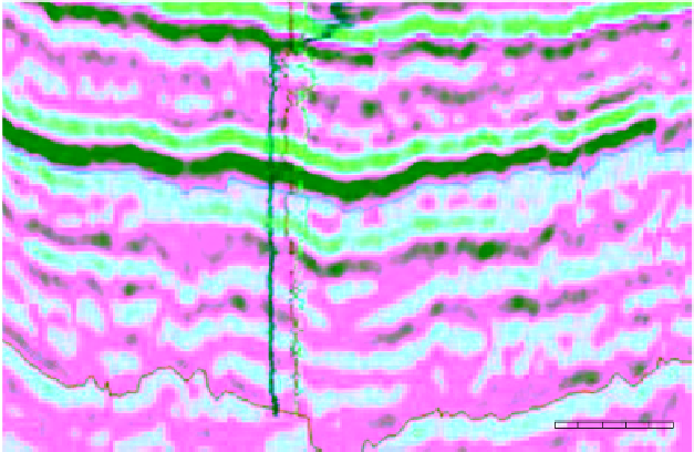
Fig. 7.
Seismic Section F of Fig. 5 calibrated to well 2/8-15. Note the correlation between the negative amplitude (orange
to red colours) of the upper channel-fill unit to the higher porosity and lower density values on the logs. Similarly,
the positive amplitude (light grey to black) of the lower channel-fill unit correspond to lower porosity and higher density
values on the logs. Amplitudes are given as unitless.
channel base here is still erosional, but less than
in the western segment.
In the central segment, the channel-fill top is
uneven and undulating, with an overall concave
upward shape (Fig. 5, Sections C and D). Passing
from the western to the central segment, the
channel cross-section changes from tabular with
steep margins to arcuate with more gentle margins
(Fig. 5, Sections B, C and D). The channel southern
margin is always erosional, truncating the subhor-
izontal parallel reflections located to the south.
The northern channel margin is erosional in the
region to the west of the boundary between blocks
2/4 and 2/7. To the east of this boundary the
channel margin is no longer clearly erosional and
exhibits instead a low gradient pinch-out geometry
(Fig. 5, Sections C and D). The transition from the
central and the eastern segment is located between
the seismic Sections D and E (Fig. 5).
The eastern segment of the channel has a
roughly uniform width, but the margins tend to be
irregular and locally indistinct, particularly
towards the ESE termination of the channel path.
At the ESE termination of the channel, bright
amplitudes delineate a splay-like geometry.
Passing from the central to the eastern segment,
the channel base loses its erosional character and
becomes only slightly irregular and undulating
(compare Fig. 5, Sections A and B with E and F).
The uppermost limit is roughly flat with only
small irregularities.
Near the border of blocks 2/7 and 2/8, the channel
southern margin is clearly erosional and steep
walled (Fig. 5E), whereas the northern margin
maintains its pinch-out geometry similar to that in
the central segment. However, both channel mar-
gins become less and less distinct towards the
channel's ESE termination (Fig. 5 F). In this terminal
area, the channel cross-section is characterised by a
gradual decrease in depth and a gradual flattening
of the base and margins, until the channel feature
flattens out and loses its identity.
WELL CHARACTERISTICS OF
THE CHANNEL FILL
Well data overview
Two wells drilled into the channel fill are of par-
ticular importance to this study: well 2/4-12 located
in the channel western segment and well 2/8-15
located in its eastern segment (Figs 4, 8 and 9).
Both these wells were cored and their core samples
were calibrated to wireline logs (Figs 8 and 9).


Search WWH ::

Custom Search