Geoscience Reference
In-Depth Information
increases with propagation time and is equal to the product
of the wave
a)
s velocity and the travel time. A surface-wave
wavefront, being con
ned to the vicinity of the surface, is
approximated by a vertical cylinder, again centred on the
source. Surface waves have lower velocity than body waves
so the two wavefronts rapidly separate, with the surface
wavefront inside that of the body wave.
Wavefronts are an actual physical phenomenon but,
although they are physically and mathematically precise,
using them to qualitatively describe the paths of seismic
waves through the subsurface can become cumbersome
when any realistic degree of complexity is introduced.
More useful in these circumstances are raypaths (often just
called rays). Raypaths are a geometrical construct depicting
the path and direction of a seismic wave as arrowed lines
genous material all the raypaths are straight lines, but they
will be curved when the elastic properties change along the
travel path. Unlike wavefronts, seismic rays do not actually
exist, but they are a powerful tool for illustrating the
propagation of waves and their interaction with the
subsurface.
'
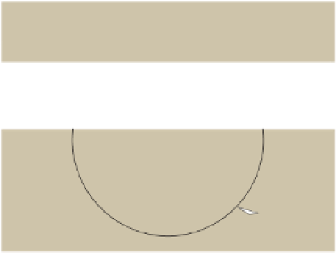
Source
A
A
Surface-wave
wavefront
Body-wave
wavefront
Map
R
Surface
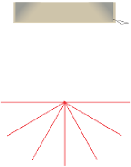
b)
Ground surface
Source
A
Z
Surface
Raypath
Surface-wave
wavefront
Cross-section
R
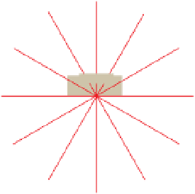
Body
A
Ground surface
Source
A
6.3.2
Fresnel volume
Body-wave
wavefront
Cross-section
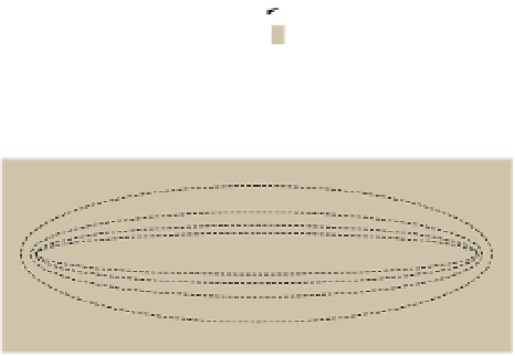
An important concept in understanding how the seismic
waves interact with the subsurface is the Fresnel volume.
There can be many similar raypaths that direct the seismic
waves to the same detector. For two distinct arrivals to be
recognisable within a seismic trace, their travel times
should differ by more than half the dominant period of
single arrival, albeit with an increased period/wavelength,
is observed.
Referring to
Fig. 6.4c
, consider the direct (shortest dis-
tance) raypath from a source to a detector that is travelled
in time T
source
-
detector
. Another ray passing through an
intermediate point C, will have a travel time that is
T
source
-
C
+ T
C
-
detector
. When this travel time differs from
that of the direct raypath by less than half the dominant
period of the seismic signal (so the difference in distance
travelled is less than half the wavelength), the arrivals will
constructively interfere (see online
Appendix 2
) and will
not be individually identi
ed within the seismic trace. The
volume of material within which this occurs is known as
the Fresnel (pronounced Fre-nel) volume and a cross-
section of the Fresnel volume, perpendicular to the direct
raypath, is known as a Fresnel zone.
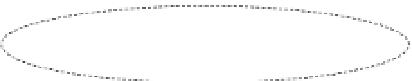
c)
Fresnel volume
Fresnel zone
Source
Detector
C
Raypath
D
Fresnel
L
d)
wer fr
Source
Detector
H
igher F
f
Raypath
Figure 6.4
Rays and wavefronts for surface and body waves produced
by a source located at the ground surface. (a) Map and (b) cross-
sections, (c) first-order Fresnel volume (ellipsoid) and Fresnel zone
(circle) for a direct raypath through a homogeneous isotopic
medium, and (d) geometry of the Fresnel volume at different
frequencies. (d) Redrawn, with permission, from Kvasnicka and
Cerveny (
1996
).


Search WWH ::

Custom Search