Geoscience Reference
In-Depth Information
location (
Fig. 5.64a
)
. The same will be true for any cross-
sections. However, if the intersection is part of a large
body, the potential
field will re
ect the shape and electrical
continuity of the body. Contours of equal potential
mapped on a planar surface will approximately correspond
with the projected shape of the body (
Fig. 5.64b
)
. It is
generally not possible to determine accurately which
particular contour corresponds with its edges. Also, the
position of the current electrode projected onto the survey
plane will not necessarily correspond with the maximum
observed potential.
If the plane in which measurements are made is a
horizontal surface, the strike direction of the body can be
inferred from the direction of elongation of the contours.
The dip and/or plunge of the body can also be estimated
from the gradients of the potential
a)
Surface
potential
A
A
Surface projection
of current electrode
A
A
Section
Current electrode
DH3
Equipotential
contours
DH2
DH1
Map
Surface projection
of current electrode
DH1
DH2
A
DH3
A
field, which can be
assessed from the spacing of the potential contours (cf.
of dip, which is also perpendicular to their elongation.
Similarly, the contour spacing in the direction of elonga-
tion indicates the plunge direction. Equivalent information
about the attitude of the body can be inferred from meas-
urements made on a cross-section.
Information about the attitude of a conductive body is
easily obtained from AP surveys provided the measure-
ments are comparatively close to the body. As the distance
between the measurement surface and the body increases,
the correspondence between the equipotential contours
and the body
b)
Surface
potential
A
A
Surface projection
of current electrode
A
A
Section
Conductor
Current electrode
Equipotential
contours
DH3
DH1
DH2
s geometry diminishes. When the distance
is large compared with its lateral dimensions, the contours
become circular and symmetrical about the body, i.e. at
great distance (depth) the body looks more like a point.
A common form of AP survey involves measuring the
electrical potential at locations adjacent to the central drill-
hole containing the current electrode, which may be within
surface or underground drillholes, or even mine galleries.
There is no fundamental difference between this approach
and that described above for surface measurements. From
the contour plots in
Fig. 5.64
it can be seen that the highest
potentials occur in the conductive body containing the
current electrode. If a second drillhole were to intersect
the same body the maximum potential measured in this
hole would coincide with the intersection(s), indicating
that the intersections are electrically connected. On the
other hand, and very importantly, the absence of potential
maxima coincident with any other intersections of poten-
tially conductive material in the drillhole indicates that
these intersections are not electrically connected to the
'
Map
Surface projection
of current electrode
DH1
DH2
A
A
DH3
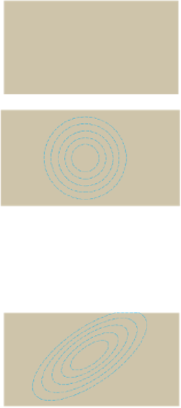
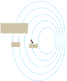
Figure 5.64
Electric
field about a buried current electrode.
(a) For a point electrode, equipotential surfaces are spherical and
concentric to the electrode, producing symmetrical potential profiles
downhole and on the surface. (b) The field of a large conductive
body mimics the body
'
s shape and orientation with body-dependent
asymmetry appearing in downhole and surface profiles.


Search WWH ::

Custom Search