Geoscience Reference
In-Depth Information
body in which the current electrode is embedded. This
ability to determine electrical connectivity between two
conductive zones can be a very powerful tool for evaluating
the extent and dimensions of a conductive body, and a
useful aid to a drilling programme. By systematically
placing the current electrode in different intersections in
different drillholes, and measuring potential variations in
other drillholes, the correct correlations between intersec-
tions may be established. Some possible situations of this
We demonstrate the application of the AP method and
the interpretation of both surface and downhole data with
examples from two different types of mineral deposit.
5.6.9.3
Interpretation pitfalls
Although the interpretation of AP data is, in principle,
straightforward, it suffers all the same pitfalls experienced
by other electrical arrays (see
Section 5.6.7
) and these
should be taken into account. For example, anisotropy is
common in obviously layered rocks such as well-bedded
sedimentary successions and metamorphic rocks such as
schists and gneisses. When there is no significant con-
ductor present, the equipotential contours will be elong-
ated in the direction of highest conductivity and their
centre may be displaced up-dip, and no longer centred
above the current electrode. The current electrode can be
deliberately located away from conductors to allow these
affects to be assessed. Conductive overburden and vari-
ations within it also complicate the interpretation, and
undulating topography distorts the electric
field, but when
necessary these effects can be accounted for in computer
When conductors are small or disrupted by faulting, or
when measurements are taken close to their margins, the
patterns of the potential anomalies are far more complex
illustrated in Greenhalgh and Cao (
1998
). When the inten-
tion of the survey is to establish continuity between
conductors, it is quite possible that the electrical continuity
between two massive sulphide intersections is via a water-
saturated fault zone rather than a continuous body of
mineralisation. Similarly, an apparent lack of electrical
continuity between two intersections in what is the same
body of mineralisation may be caused by a zone of poorly
conductive minerals, whether gangue or sulphides such as
sphalerite (an electrical insulator). Quite minor faulting
can also break the electrical continuity.
Measurements of
potential variations
a)
I
V
Downhole
potential
Current
electrode
DH2
DH1
DH2
Depth
b)
I
V
Downhole
potential
Current
electrode
DH2
DH1
DH2
Depth
c)
V
I
Downhole
potential
Projection of
current electrode
Current
electrode
DH2
5.6.9.4
Example - Woodlawn polymetallic
massive sulphide
This example illustrates the response from a moderately
dipping conductive massive sulphide body with complex
geometry and high contrast with its host rocks.
Figure 5.66
shows the results of an AP survey at the Woodlawn
Cu
DH1
DH2
Depth
Conductive zones
Conductive intersection
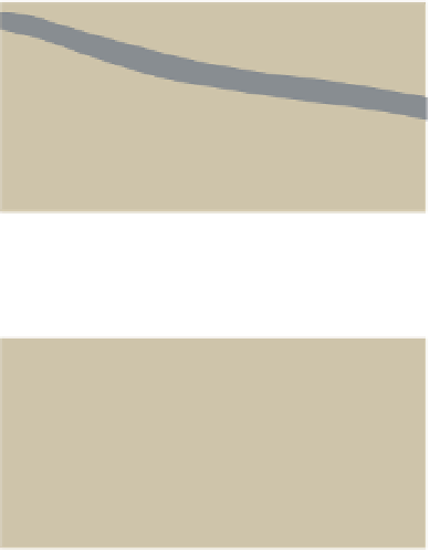
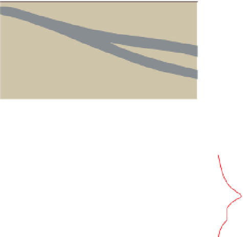
Figure 5.65
Schematic illustration of downhole applied potential logs
used to establish electrical continuity of conductive stratigraphic
units between drillhole intersections for three different cases.
(a) Both intersections electrically connected to the energised
intersection; (b) connectivity only to the upper intersection; and
(c) both intersections electrically disconnected from the energised
intersection. Electrical connectivity is indicated where the potential
is strongest.
Zn deposit in New South Wales, Australia
(Templeton et al.,
1981
). The deposit is of volcanic-hosted
massive-sulphide type, and the ore forms a west-dipping
lens in a succession of pelitic and pyroclastic rocks and
-
Pb
-


Search WWH ::

Custom Search