Geoscience Reference
In-Depth Information
Porous flow
Channel flow
RT instability
Diapiric ascent
g
µ
µ
µ
a
R
r
µ
D
R
2
B
a
2
12
D
2
m
r
2
4.5
Δ
r
g
m
Δ
r
g
Δ
r
g
m
Δ
r
g
|
u
| =
|
u
| =
|
u
| =
|
u
| =
m
n
−
1
f
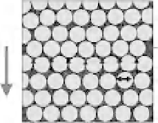
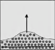
Fig. 13.3
Ascent mechanisms of a light liquid or liquid-bearing region, and their representative flow velocities
|
under the gravitational field. In porous flow, the liquid phase with viscosity
μ
percolates through the solid grains of
aradius
R
(
B
is the constant involved in permeability and
φ
is the fluid fraction), whereas in channel flow, the
liquid phase ascents a channel of width
a
. In Rayleigh-Taylor (RT) instability and diapiric ascent, a liquid (aqueous
fluid and/or melt) phase-bearing region ascends because the region is less dense than the surrounding part. See the
main text for more details.
|
v
with significant dehydration broadly corresponds
to the location of magmatic-hydrothermal arc.
In the following section, fluid distribution and
transport beneath the arc are discussed.
and is ignored. In Rayleigh-Taylor (RT) instabil-
ity, a wave-length
D
with the fastest growth rate
and a relatively large viscosity of the deforming
region constrain the velocity. In addition, the den-
sity contrast
ρ
in porous flow is directly related
to that between solid and fluid phases (
ρ
s
−
f
)and
the fluid fraction
φ
affects permeability, whereas
ρ
is related to
φρ
s
−
f
in RT instability.
We consider several plausible cases to com-
pare the characteristic velocity and migration
time scale over a distance of 100 km (from the
subducting slab to the surface). The slab-derived
fluid forms an aqueous fluid-bearing or partially
molten region along the slab and in the mantle
wedge. These regions may develop RT instability
or diapiric ascent (Figure 13.3), which competes
with the segregation processes by porous and/or
channel flow, since the fluid is thought to form
a connected network beneath the volcanic arc
(Mibe
et al
., 1999). RT instability of a scale
D
or
the diapir of a radius
r
can grow and ascent until
fluid segregation completes. The critical condi-
tions have been estimated based on the equations
shown in Figure 13.3:
D
critical
=
13.2.2 Mechanism of water transport
Figure 13.3 shows several general schemes for as-
cent mechanism of a light liquid or liquid-bearing
(but mostly solid) region. Representative ascent
velocities are determined by the balance between
buoyancy and the viscous resistance. Accordingly
they are expressed in a common form, being pro-
portional to the density contrast
ρ
, the square
of characteristic length (
R
,
a
,
D
,
r
), and inversely
to the viscosity
μ
that governs the flow (Figure
13.3). These parameter values appropriate for sub-
duction zone settings may differ significantly
corresponding to the respective mechanisms. For
example, in porous flow, the mineral grain size
R
and the viscosity of permeable fluid
μ
govern
the velocity. The porous flow in the mantle may
accompany compaction of the deformable matrix.
The compaction length, which measures a thick-
ness of a mechanical boundary layer that expells
the fluid (aqueous fluid/melt) at the bottom of the
fluid-bearing two-phase region, is
100 to 368 km
10
19
is obtained when
μ
=
Pa s and
ρ
=
0.5 to
25 kg m
−
3
∼
for RT-instability,
μ
=
0.1 Pa s and
100 m in the
mantle (McKenzie, 1984). Therefore, compaction
does not primarily affect the following arguments
500 kg m
−
3
ρ
=
for porous flow have been as-
sumed with
φ
=
0.001 to 0.05,
n
=
3and
B
=
1000.