Geoscience Reference
In-Depth Information
200
200
400
400
600
600
1000
800
600
400
200
0
1000
800
600
400
200
0
km
km
(a)
(b)
u0 = 2.25 cm/yr, age = 130 Ma
u0 = 2.25 cm/yr, age = 15 Ma
0
0
200
200
400
400
600
600
1000
800
600
400
200
0
1000
800
600
400
200
0
(c)
(d)
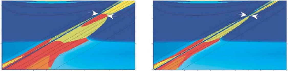
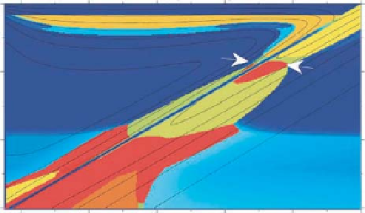
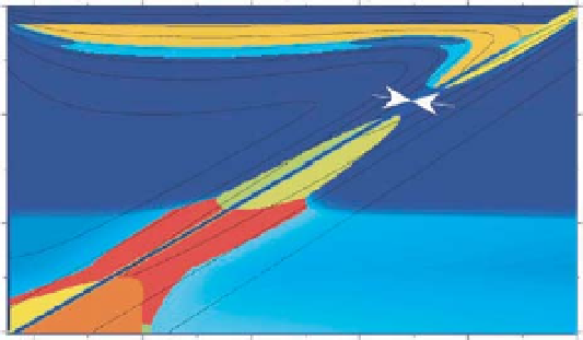
Fig. 13.2
Distribution of maximum H
2
Ocontent(
C
max
H
2
O
) in subduction zones associated with the subducting plates of a subduction angle of 30
degrees and different ages of the subducting plates (15 to 130 Ma) and subduction velocities (2.25 to 9.0 cm/year). The color scale is the same as in
Figure 13.1. Two white arrows in each figure indicate the approximate location of the choke points across the subducting slab. First, the steady
state flow field and the temperature distribution have been calculated based on a standard set of conservation equations for momentum and
energy of mantle flow with temperature dependent viscosity as in Iwamori (2004). The temperature contours are shown by solid lines with an
interval of 200 degrees. An analytic corner flow solution is assumed on the backarc side boundary and a constant velocity is assumed within the
subducting plate (entire region below the diagonal interface between the mantle wedge and the subducting plate). Then, distribution of
C
max
H
2
O
has
been calculated. The thermal boundary conditions are as follows: a surface temperature of 0
◦
C; an error function gradient for a given plate age
and an adiabatic gradient underneath for the oceanic side boundary, with a potential temperature of 1300
◦
C; an error function gradient
corresponding to a plate (backarc basin) age of 20 Ma for the backarc side boundary (e.g., corresponding to formation of a backarc basin such as
Japan-sea) with a potential temperature of 1300
◦
C; zero heat flux at the bottom. The solid lines indicate the temperature contours with the
interval of 200
◦
C. Reproduced with permission of Elsevier. (See Color Plate 18).