Information Technology Reference
In-Depth Information
w
h
ˀ
(
w
h
)
8
w
m
ˀ
(
w
m
)
w
1
ˀ
(
w
1
)
7
v
6
ˀ
(
v
)
(a)
5
4
w
h
y
max
(
v
)
3
w
m
w
1
2
v
y
min
(
v
)
1
x
min
(
v
)
x
(
v
)
x
max
(
v
)
(b)
(c)
(d)
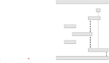
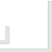
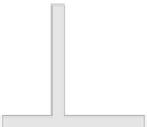
Fig. 7.
(a) Successors
w
1
,...,w
h
,...,w
m
of
v
whose ordering in the embedding is bitonic with
respect to the y-coordinates. (b) Creating a pole at
w
h
, i.e., the highest successor, and pulling the
bars of the remaining towards it. (c) Visibility representation for the running example. The edges
to the highest successor are drawn solid. (d) The resulting T-shaped contact representation.
row that corresponds to its rank in
ˀ
.SeeFigure 7c for such a visibility representation
for the running example. Although a visibility representation can be derived this way
for any
st
-ordering, we may now benefit from the property that
ˀ
is a bitonic
st
-order.
Since for every
v
V
,
S
(
v
) is bitonic with respect to
ˀ
, by construction it is also
bitonic with respect to the y-coordinates, i.e., the successors are located above
v
in an
increasing and then a decreasing staircase pattern. See Figure 7a for an illustration.
By using a simple trick, we now transform this wedge-like structure into a rectilin-
ear T-shaped polygon. The idea is straightforward: We create a vertical segment on top
of the horizontal bar that reaches all the way upto
w
h
, i.e., the highest successor of
v
. Afterwards we pull the bars of the remaining successors towards this pole. See the
arrows in Figure 7b for a sketch of the idea. Notice that in case of a non-bitonic
st
-
ordering,asingle pole is not sufficient. More specifically, let
x
min
(
v
) (
x
max
(
v
)) denote
the left (right) border of the upside-down T representing
v
and
x
(
v
) the horizontal off-
set of the pole. Furthermore, let
y
min
(
v
) and
y
max
(
v
) denote the vertical offset of the
horizontal bar and the upper border of the pole, respectively. Then, for every
v
∈
∈
V
with
S
(
v
)=
>y
(
w
m
)
holds, we create the vertical segment by choosing
x
(
v
)=
x
((
v,w
h
)),where
x
(
v,w
h
)
denotes the x-coordinate of (
v,w
h
) in the visibility representation. Furthermore, we
set
y
max
(
v
)=
y
min
(
w
h
). For the remaining successors
w
i
with 1
{
w
1
,...,w
h
,...,w
m
}
in which
y
(
w
1
)
<
···
<y
(
w
h
)
>
···
i<h
, i.e.,
those located to the left of the pole, we establish contact with the pole from the left
by choosing
x
max
(
w
i
)=
x
(
v
). In a symmetric manner, we set
x
min
(
w
i
)=
x
(
v
) with
h<i
≤
m
for those successors that are located on the right. Notice that
x
min
(
v
)
and
x
max
(
v
) are only defined in the case where there exists such a pole on both sides.
Otherwise, we have to ensure that the horizontal bar of
v
covers at least the attaching
poles from below. Hence, for every
u
with
v
≤
∈
S
(
u
) and
ˀ
(
v
)=max
w∈S
(
u
)
{
ˀ
(
w
)
}
,
i.e., all
u
for which
v
is the highest successor, we set
x
max
(
v
)=max
{
x
(
v
)
,x
(
u
)
}
and
x
min
(
v
)=min
.See
v
3
and
v
5
in Figure 7c. The final contact representa-
tion for ourrunning example is shown in Figure 7d.
{
x
(
v
)
,x
(
u
)
}