Agriculture Reference
In-Depth Information
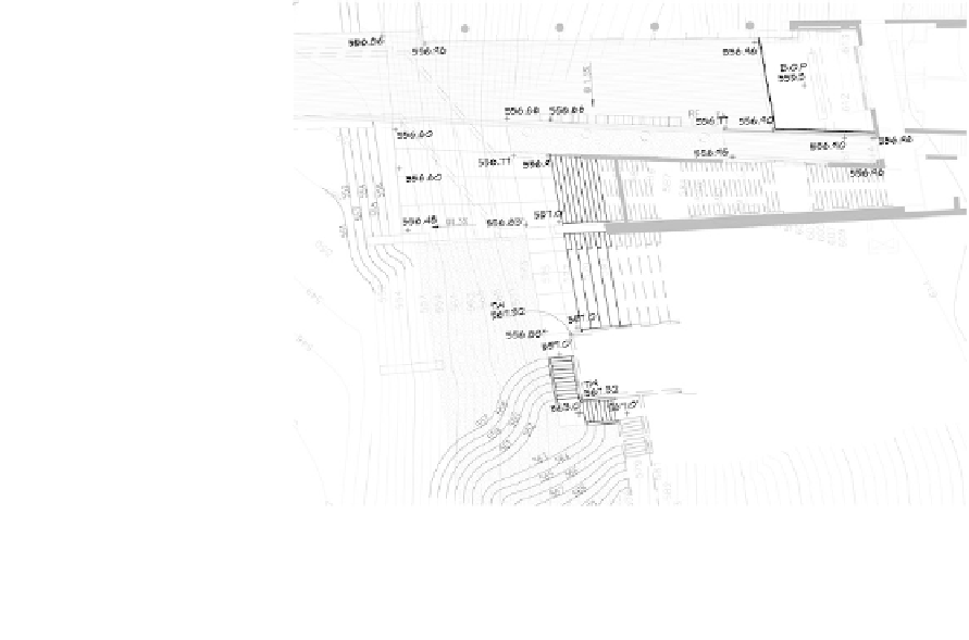
Figure 13.20 is a portion of a professional site-grading plan. Notice
the use of contours in the landscaped areas and spot elevations for the
hardscape. Exiting contours are shown as dashed lines, and proposed
contours are solid lines. The plan guides the work of the grading con-
tractor. The grading plan package would also include multiple section
drawings. To guide the actual earth-moving activities of the grading
contractor, a series of cross sections following a grid system would be
established by a team of land surveyors. Wood stakes are placed in the
ground along the grid lines with elevations marked on the stakes corre-
sponding to grade elevations found in the grading plan. Wood surveyor's
stakes are typically placed at the intersections of the grid lines and at
key locations such as at building corners or critical elevations where the
designer wants to control the elevation of landscape or paved surfaces,
and needs to indicate heights of walls or other design elements. The
elevation is written directly on each stake, with the proposed elevations
interpolated by the land surveyor or taken directly from the grading plan.
In the next chapter various approaches to handling storm water
will be presented.
Figure 13.20
Grading plan detail: Tarrant County College District, East Trinity
Campus, Fort Worth, Texas
Courtesy of studio outside And binG thoM ArChiteCts