Agriculture Reference
In-Depth Information
of the museum shown in Figure 13.18. Slope indications would also be
shown along swales and where steep cut and fill slopes occur. Technical
sections would also be provided where the designer wishes to ensure
that the contractor understands the grading design intent for subtle or
critical earth forms and slope changes.
conStruction Sequence for a BuS SheLter
The contractor lays out the construction area
using the staking or layout plan included
in the construction document packaged
prepared by the landscape architect. The
staking plan is the basis for the contractor
to establish the locations of all the design
elements. The contractor may hire a land
surveyor to locate the design elements fol-
lowing the staking plan or may do the work
with in-house employees. After staking is
completed, the contractor does rough grad-
ing then constructs the wood forms follow-
ing the staking plan and grading plan. The
forms contain the poured concrete and are
positioned on the ground conforming to the
elevations shown on the plan. The contrac-
tor sets the top of the forms following the
spot elevations shown on the site-grading
plan. Stakes are installed to secure the wood
forms so they do not move or bow out when
wet concrete is poured.
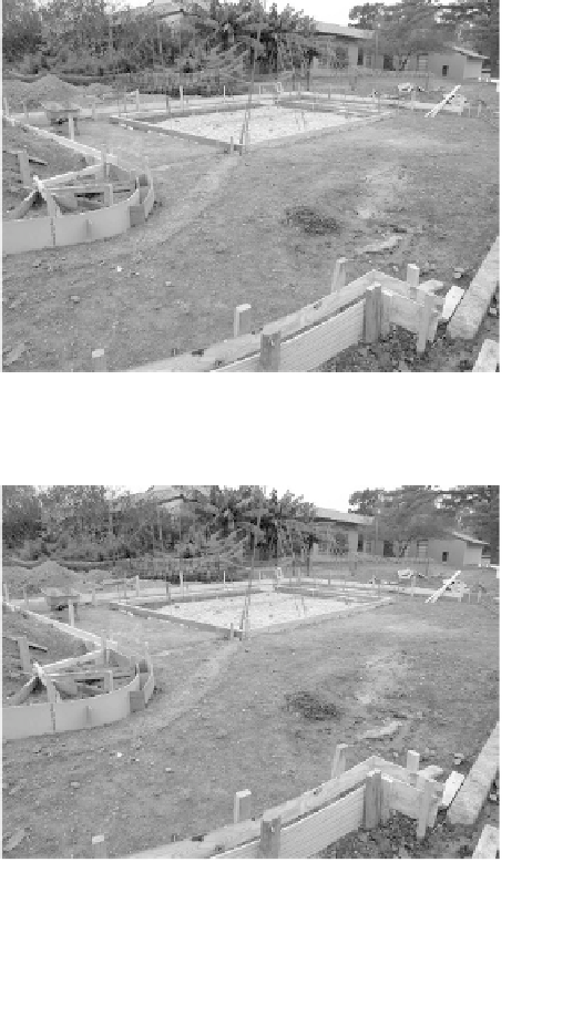
The sequence followed in erecting the
forms and setting the elevations can be seen
in Figures 13.19-A through Figure 3.19-J. Fig-
ures 13.19-A and 13.19-B show the overall
layout for a bus shelter next to a street. The
center area of Figure 13.19-A is the location
Figure 13.19-a
Wood forms to contain concrete in the
construction of a bus shelter area
Figure 13.19 - B
Wood forms for ADA access ramp and
walk to lead to bus shelter