Agriculture Reference
In-Depth Information
maybe a pool with deck. If this is the case,
the swale could be 20 to 30 feet away from
the pad so that the ground slope away
from the pad might be set at 1% or 2%.
Item B represents the width of the
swale. The width could vary along the
length of the swale and should be sized so
that the side slope is no greater than 2% to
5% (as a rule of thumb, it could be greater
on less erosive soils).
The final steps (see Figure 12.6-F) are
to reposition the contours 105 and higher.
Notice that in this example contour 105 is
modified, as the 104 contour was repositioned to cross over the 105 con-
tour. If other contours were affected they would need to be modified as
well. The area where the 105 contour is modified is called the back slope
and—in this case—is creating cut. In modifying the 105 the designer
should create a back slope that will not cause erosion if too steep.
99
A
100
101
102
104 .3
103
SHP=104 . 1
104
A
106
105
Figure 12.6-F
Step Six
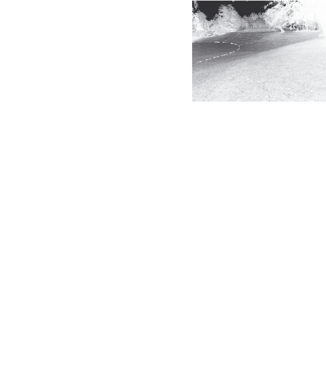
creatinG a drainaGe SWaLe
A drainage swale can be created and placed in the landscape with the
purpose of collecting surface water and directing it to another location
on a project site. The water could be directed to an on-site pond, a neigh-
borhood drainage canal, or a catch basin that is connected by an under-
ground pipe to a storm water collection system. A constructed drainage
swale could also be adapted into a system of bioswales that in turn
might be components of an on-site detention or retention pond system.
While a simple swale is created solely for collecting and directing water,
a bioswale is designed for the added purpose of slowing down water
flow to allow the water to percolate into the soil, eventually recharging
a subsurface aquifer, or into the water table. A bioswale is also designed
to incorporate plantings of species that are selected to uptake a variety
of pollutants dissolved in or carried by the water entering into the swale,