Information Technology Reference
In-Depth Information
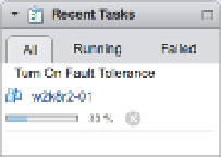
Figure 7.30
vSphere FT must
convert existing
virtual disks to
h ick Provision
(eagerzeroedthick)
format as it's pow-
ering on for the
fi rst time.
5.
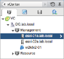
Once the process is complete, the VM's icon in the Navigator tree will change. Figure 7.31
shows a VM that has been enabled for vSphere FT.
Figure 7.31
h e darker VM
icon indicates
that vSphere FT is
enabled for
this VM.
And that's it. It is literally that simple—at least on the surface.
Behind the scenes, after vSphere FT is turned on, vCenter Server will initiate the creation of
the secondary VM by using a special type of vMotion. Both the primary and secondary VMs
will share a common disk between them, and using VMware vLockstep, vSphere FT will then
be able to keep the VMs in sync. vSphere FT uses a network connection between the ESXi hosts
to keep the primary and secondary VMs in sync (recall from our earlier discussion of require-
ments that the ESXi hosts must have a Fault Tolerance logging connection established; Chapter 5
provides more detail on how to coni gure this network connection). Only the primary VM will
respond to other systems across the network, which leaves the secondary VM a silent partner.
You can almost compare this to active/passive cluster coni guration in that only one node owns
the shared network at a time. When the ESXi host supporting the primary VM fails, the second-
ary VM takes over immediately with no break in network connection. A reverse ARP is sent to
the physical switch to notify the network of the new location of the VM. Does that sound famil-
iar? It is exactly what vMotion does when the VM switches to a new host. Once the secondary
VM becomes the primary, the creation of the new secondary VM is repeated until the sync is
locked. After the sync is locked, as shown in Figure 7.32, you'll see green icons.
Figure 7.32
h e vSphere Web
Client shows
vSphere FT status
information in the
Fault Tolerance area
on the Summary
tab of a VM.