Graphics Programs Reference
In-Depth Information
If you try stretching the rectangle in various ways (from the upper-left corner, for ex-
ample), you can see that only the bottom and right sides are constrained to 10 units in
length. You could add two more linear dimensional constraints to the unconstrained
sides, but then you'd have to remember to edit both dimensions. Rather than constrain-
ing both sides to be 10 units long, the way to maintain design intent is to make both
sides equal in length.
You can make the two sides equal using either dimensional or geometric con-
straints. It's sometimes a good idea to apply some geometric constraints to your
drawing so objects are at least a little locked down. In fact, in a real-world work-
flow, you'd be using both geometric and dimensional constraints as you produce
your design.
I cover geometric constraints in a little more detail in the “Understanding Geometric
Constraints” section later in the chapter, but for now, I'm going to apply three geometric
constraints so the drawing behaves more predictably.
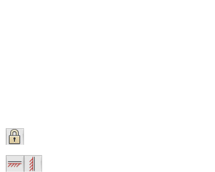
1. On the Geometric panel of the Parametric tab, click Fix (the padlock
icon) and click the lower-left corner of the rectangle.
2. On the Geometric panel, click Horizontal and click the bottom
side of the rectangle. Then click Vertical and click the left side.
Icons appear near the drawing geometry, showing that those three geometric con-
straints are active (see Figure 19-6 a few pages ahead).
I explain those icons — and geometric constraints, in general — in the next section,
but I'm going back to dimensional constraints to finish this drawing.
3. On the Dimensional panel of the Parametric tab, click Linear and add a dimen-
sional constraint to the top horizontal line.
4. Click to locate the dimension, type
d1
, and press Enter when AutoCAD prompts
for the dimension text.
Instead of having numeric values like the first two linear constraints, this new di-
mensional constraint displays
fx: d3=d1
.