Graphics Programs Reference
In-Depth Information
The Entity Info dialog box is also shown. It gives you the component and
layer of the selection; in this example, the component is Numbers and
the layer is “0-numbers.” Also the Outliner dialog box shows the structure
of the groups/components. You can find any group or component in the
model from the Outliner. There are many options in the Outliner; just right-
click a group/component to see the options.
Tip
We have created a full library of 3D structural steel shapes. If these are all
created with uniform length and components axis, then substituting one
shape for another is straightforward using the component context menu
or the Component browser. We recently created dynamic components that
have all steel dimensions embedded in them.
Step 2: Designing and Modeling New Process
Plant Options
Goals
: To create a process flow diagram (PFD) and conceptual model of
the new process; to obtain client approval of the proposed design.
Inputs
: Preliminary process flow diagram, the existing facility model
developed in step 1, and basic knowledge of the proposed process
equipment.
Tools
: SketchUp 7.1 and GoToMeeting (web conferencing).
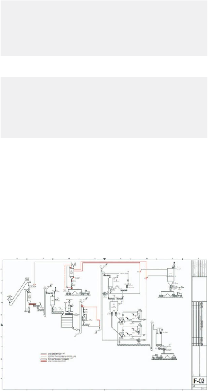
FiG 7.6
Process flow diagram created
in LayOut.

Search WWH ::

Custom Search