Graphics Programs Reference
In-Depth Information
Based on client input, review, and discussion, preliminary PFDs are created.
Here, we discuss the creation of PFDs with LayOut 2.1.
We then model the process with SketchUp. SketchUp allows us to quickly
model the preliminary process based on the PFD. As the model is created,
process flow changes to accommodate the physical constraints of the
project, which are realized while modeling the process. The PFD devel-
opment and modeling are very interactive processes. While working
simultaneously on the process and the model, design options quickly
become apparent.
In traditional engineering projects, PFDs are developed along with simplistic
2D general arrangement drawings. The drawings are time consuming to
create. In the traditional design process, this is an essential step. These
2D drawings are reviewed or marked up by the client, and returned to the
engineer for approval or additional development. The 3D SketchUp models
and web conferencing have eliminated this step for us.
Now, we review a model of the project. This takes much less time than creat-
ing 2D drawings. Usually, the review is done online in a web conference. The
SketchUp model is reviewed, including all the model options, and changes are
made during the meeting, all online. Approvals are usually given during these
meetings. This has eliminated the traditional design/drawing phase of project
design.
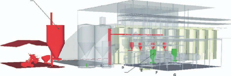
Option 2
Option 1
FiG 7.7
Process options in existing model.
At this step in the project, we start setting up display controls on the model
using Scenes. We also start thinking about what we will be showing in the
construction documents. At the end of the step, we would like the layering of
the model to be 80%-90% complete.

Search WWH ::

Custom Search