Biomedical Engineering Reference
In-Depth Information
(A)
(B)
Diameter (nm)
Diameter (nm)
(C)
(D)
Diameter (nm)
Diameter (nm)
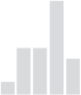
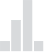
FIGURE 18.10
Change of fiber morphology and diameter at different stages of preparation of
-TCP@CNFs: (A) as-spun
nanofiber, (B) after 100% hot-stretched, (C) after preoxidation, and (D) after carbonization.
β
TEP solution. The solution is stirred at room temperature for a certain time to generate a CaP com-
plex. Then a certain amount of the prepared sol
gel solution is added to the pre-prepared PAN/
DMF solution and stirred to obtain a homogeneous solution. This solution is then electrospun and
the as-spun nanofibrous membranes are collected in an aluminum roller. The as-spun nanofibrous
membranes are stabilized at 533 K for 30 min in air and then carbonized at 1373 K for 2 h
in N
2
surrounding to obtain the
-TCP@CNF hybrid nanofibers.
In
Figure 18.10
, the macroscopic and microscopic changes of
β
-TCP@CNFs in different stages
of preparation process are shown. It can be seen clearly that the average fiber diameters continue to
decrease as the as-spun composite fibers are treated with hot-stretching, pre-oxidation, and finally
carbonization. The pre-oxidation is performed at the temperature range of 250
β
300
o
C, cyclization
takes place in the procedure, and some hydrogen atoms are released. Therefore, the white PAN
mats change into brown and the average fiber diameter further decreases. As the temperature is fur-
ther increased above 600
o
C, denitrogenation will happen and CNFs are formed. At the same time,
the CaP crystals will result from the precursors with the removal of organic component. After car-
bonization, nanoparticles can be observed on the fiber surface in the SEM photos (
Figure 18.11
).
Via TEM observation, numerous nanoparticles can be seen inside the fibers.
To further reveal the crystallographic microstructures of CNFs and
-TCP nanoparticles in
hybrid CNFs, HR-TEM characterizations are performed. The HR-TEM image of a typical CNF dis-
tinctly shows the disordered lattice structure with low degree of crystallization. The presence of
two well-resolved concentric diffuse rings (
Figure 18.12A
), corresponding to the (0 0 2) and the
β