Biomedical Engineering Reference
In-Depth Information
When.coils.operate.at.low.frequency,.their.
Q
.factor.is.deined.as.
Q
.=.ω
L
/
R
,.where.ω.is.
frequency,.
L
.is.inductance,.and.
R
.is.series.resistance..As.frequency.increases,.frequency-
related.effects,.including.skin.effects,.proximity.effects,.and.self-resonance,.modify.both.
L
.and.
R
,.dramatically.degenerating.the.
Q
.factor..According.to.Yang.et.al.,
43
.a.formula.pre-
dicting.the.
Q
.factor.is
2
π
f L
R
1
1
−
+
f
/
/
f
2
2
Q f
(
)
=
self
.
(16.3)
f
2
f
h
2
.
where.
f
h
.is.a.parameter.to.quantify.the.impact.from.proximity.effect.(skin.effect).and.
f
self
.
is. the. coil's. self-resonant. frequency..
f
h
. and.
f
self
. are. expressed. by. geometry. and. physical.
parameters,.whose.expressions.are.shown.in.Yang.et.al.
43
.For.any.given.coil,.there.is.an.
optimal.frequency.
f
peak.
that.has.the.maximal.
Q
..To.maximize.the.power.eficiency,.
f
peak.
of.
the.coil.pair.should.be.designed.in.accordance.with.the.power.carrier.frequency..Based.on.
Equation.16.3,.an.analytical.form.of.
f
peak.
is
1
1
3
≈
+
.
(16.4)
f
2
f
2
f
2
peak
h
self
.
Equation.16.4.represents.a.key.design.equation.and.a.closed-form.analytical.solution.for.
f
peak
..With.this.single.equation.of.merit,.the.maximum.
Q
.and.the.maximum.eficiency.of.the.
telemetry.system.can.be.determined..By.changing.the.design.parameters,.one.may.tune.
f
peak.
close.to.the.target.frequency.and.maximize.the.power.eficiency.of.the.telemetry.
16.5.2 Multiple Power Supplies
A.high.supply.voltage.speciication.of.the.retinal.implant.system.is.derived.from.the.com-
pliance. voltage. of. the. stimulator.. However,. a. majority. of. circuit. blocks,. e.g.,. digital. con-
trollers,. data. demodulator,. oscillator,. and. part. of. the. stimulator,. can. operate. at. a. much.
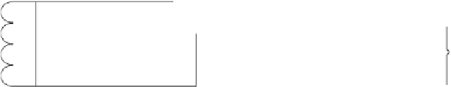
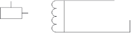
lower. voltage. level. to. reduce. the. overall. power. consumption.. As. shown. in. Figure 16.7a,.
a.high-eficiency.DC/DC.buck.converter.is.a.possible.solution.to.convert.a.higher.supply.
voltage.to.a.lower.supply.voltage.
However,.this.approach.requires.additional.off-chip.components.(inductors),.imposing.
burdens.on.system.integration.and.miniaturization..Through.use.of.a.cascaded.resonant.
tank.that.reuses.the.power.coil,.it.is.feasible.to.provide.four.rectiied.and.regulated.volt-
ages.(±12V,.±1.8V).with.a.shared.return.path,.as.illustrated.in.Figure 16.7b..Compared.to.
VHSin
VddH
VddH
VHSin
12 V
12 V
DC/DC
Convertion
VssH
VssH
VddL
VddL
1.8 V
-12 V
-12 V
1.8 V
VLSin
VssL
-1.8 V
Gnd
(a)
(b)
FIGURE 16.7
Rectiier. comparison.. (a). A. conventional. resonant. tank. provides. four. supplies. (VddH,. VssH,. Vddl,. and. Vssl).
through.DC/DC.conversion..(b).A.cascoded.resonant.tank.provides.the.same.four.supplies,.but.without.DC/DC.
conversion..For.illustration,.regulators.and.their.required.voltage.overheads.are.ignored.in.the.picture.