Graphics Programs Reference
In-Depth Information
Adding Sides to the Part
Flanges are typically features that are bent from the base. The Flange tool
includes nearly every conceivable option for creating your features.
Certification
Objective
1.
Verify that the 2013 Essentials project file is active, and then open
c10-03.ipt
from the
Parts/Chapter10
folder.
2.
Locate and start the Flange tool in the Create panel of the Sheet
Metal tab or the marking menu.
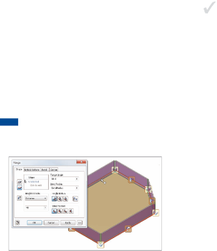
3.
On the Shape tab, click the Loop Select mode, and click the front face
of the part to highlight all edges and get a preview of the feature.
4.
Set the Height Extents value to 40. If the flange preview is not in the
same direction as Figure 10.6, hold the Shift key, deselect the lower
edge, and then reselect the edge of the top face.
TIP
When selecting edges for placing flanges, it's important to be
aware of which edge you're selecting. The height is based on the edge
you select. If you want the height measured from an outside face, you can
reverse the direction of the flange to pass back through an existing face.
FIGURE 10.6
Select the portion of the sketch from which to
create the face.
5.
Click Apply to create the new flanges.
6.
Switch to Edge Select mode, and set Height Extents to 20.
7.
Click the inside edges of the previously placed flanges, as shown in
Figure 10.7. If you cannot select an edge, click next to 0 Selected to
enable selection mode.


Search WWH ::

Custom Search