Graphics Programs Reference
In-Depth Information
By creating a series of sheet metal defaults and saving them in a template, you
can save time by not re-creating the styles over and over.
Building Sheet Metal Components
Even though the Inventor sheet metal tools are limited to components that can
be made with break press operations, the variety of components that can be made
with this process is enormous. As a result, there are a large number of sheet metal
tools to accommodate the different features that are commonly needed.
Creating a Basic Face
The Face tool looks much like the Extrude tool, but with sheet metal features,
there is no need to input a thickness from the material because that is deter-
mined by the sheet metal default style.
Certification
Objective
1.
Verify that the 2013 Essentials project file is active, and then open
c10-02.ipt
from the
Parts/Chapter10
folder.
2.
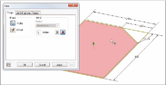
Start the Face tool from the Create panel of the Sheet Metal tab.
3.
There is more than one closed profile, so no profile is automatically
selected. Select the larger portion of the sketch, as shown in Figure 10.5.
4.
Click OK to create the face.
FIGURE 10.5
Select the portion of the sketch from which to create the face.
TIP
A face feature is frequently the base feature for sheet metal parts.
You should try to use it to define the overall shape of your part. Face fea-
tures can be added to a part at any time.


Search WWH ::

Custom Search