Graphics Programs Reference
In-Depth Information
The gear will be solid with no opening for the shaft or accommo-
dation for reducing the weight of the gear. Since the part is a solid
model, you can use any solid modeling tool to change it, but in this
example, you will create the shaft accommodation using the Key
Connection Generator.
3.
Click the Return icon on the Ribbon or click Finish Edit in the mark-
ing menu to return to the assembly.
4.
Switch the Ribbon to the Design tab, hold the Ctrl key, and click the
Key Connection tool in the Power Transmission panel.
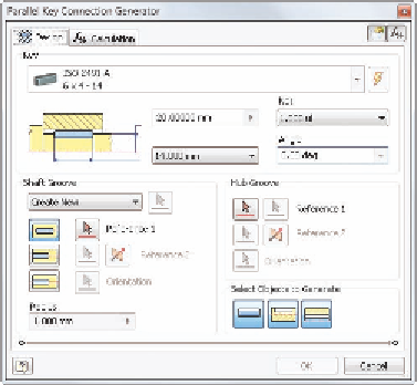
The Parallel Key Connection Generator dialog box (Figure 8.14) has
some similarities to the Bearing Generator dialog box. The process is
straightforward. Select the type of key you want, and then tell it what
kind of groove you want for the shaft and hub or if you want one.
FIGURE 8.14
The Parallel Key Connection
Generator dialog box default values
5.
At the top of the dialog box, the current key standard is displayed.
Click the down arrow at the end of this space to open the selection
dialog box.
6.
At the top of the dialog box showing the available key types, click the
Standard drop-down, and select ANSI to limit the options.
7.
Click the Rectangular or Square Parallel Keys type.

Search WWH ::

Custom Search