Graphics Programs Reference
In-Depth Information
2.
The Hole Table flyout is located in the Table panel on the Annotate
tab. Expand the list, and click the Hole View option.
3.
Select the drawing view of the part.
4.
Set the origin location to be the center of the large hole in the lower
right of the part.
5.
When the preview of the table appears, drag it near the top of the title
block against the left edge of the border, and click to place it.
Closer inspection of the drawing will show that it has labeled each
of the holes with an alphabetical hole class and then a number that
counts how many holes of that size are in the view. The table shows
those hole names along with the dimensional information for plac-
ing the holes, as well as the description of each hole. To simplify the
table, you can group the descriptions together.
6.
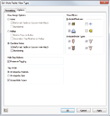
Double-click the hole table to open the Edit Hole Table: View Type
dialog box. Select the Combine Notes radio button (Figure 6.28) in
the Row Merge Options group.
7.
Click OK to update the table. Figure 6.29 shows the result.
FIGURE 6.28
Merging hole descriptions can
make the table less confusing.
Search WWH ::

Custom Search