Biomedical Engineering Reference
In-Depth Information
2
Green
UV
Opponent
1.5
1
0.5
0
-0.5
-1
-1.5
-2
-100
-50
0
50
100
Angle (deg)
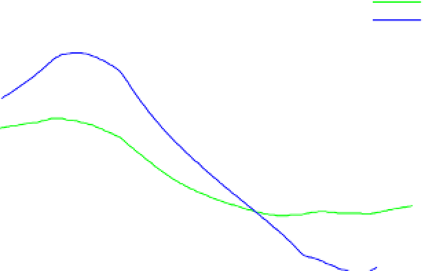
FIGURE 9.18
The signals from the photodiode configuration when the simulated body holding the ocelli was rolled.
Ideally, each curve, representing the difference between left and right signals, would pass through the origin. Only the
spectrally, opponent signal crossed the origin when wings were level. Biases away from the origin at zero roll angle were
caused by the position of the sun.
2
Green
UV
Opponent
1.5
1
0.5
0
-0.5
-1
-1.5
-2
-100
-50
0
50
100
Angle (deg)
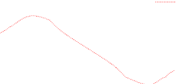
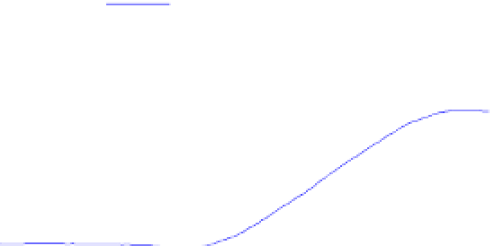
FIGURE 9.19
The signals from the photodiode configuration when the simulated body holding the ocelli was yawed.
As the fields of view of the ocelli pan around the horizon, the difference between left and right light levels should be zero
or close to zero. Due to the asymmetrical light distribution caused by the sun, the ultraviolet and green diode signals do not
remain equal on the left and right sides. The sensor channel using the difference between left and right spectrally opponent
signals did not deviate substantially from zero throughout the yaw motion.