Graphics Programs Reference
In-Depth Information
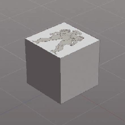
FIG. 5.9
The cube with the front model sheet applied.
The top of the cube looks i ne, if a little out of proportion, so we will use this
part for our model sheet, meaning we don't have to mess around with UV
editing at this stage.
●
Switch to the top viewport and select the cube.
●
By default the Move manipulator will be active, so select the
Scale
Manipulator
from the bottom tool bar or press
E
.
(Tip: Remember that W, E, and R will switch between the Translate, Scale, and
Rotate manipulators. )
●
Now adjust the size of the cube so the image is correctly proportioned
(Figure 5.10). As a guide, the image should be 4 grid units wide and 10
grid units tall.
T h e i rst image plane is ready, but is still in cube form and not correctly
orientated. To get a precise rotation we will turn to the
Numerical Editor
for help.
(Tip: For precise rotations you could also use the Snapping Manipulator
(SelectionManipulator ToolSnap). )
●
G o t o
Editor/Options
>
Numerical Editor
. This will open the window
shown in Figure 5.11 .
●
All we need to do at this stage is rotate the cube
-90
in the
Rotation X
box
(Figure 5.12). You can do this by manually typing the value into the editor,
or by clicking with your mouse button in the input box and dragging to
interactively edit the value.
(Note: When you deselect the Numerical Editor, the value will reset to 0, so be
sure you entered the correct value before you move on.)
With the cube's orientation and scale i xed, we can now remove the
redundant polygons.