Graphics Programs Reference
In-Depth Information
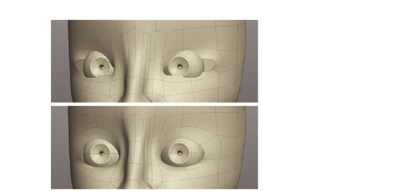
FIG. 8.24
Bring the eyes Into the
scene and adjust the eye sockets to i t.
●
With the faces still selected, apply another
Extrude
.
●
This time, move the selected faces back into the eyeball. This will act as the
pupil, as this area will be in shadow and will be nice and dark.
●
Finally,
Bevel
the rim around the opening to the pupil to harden the edge
slightly.
●
Bring the eyeball into your scene and position it roughly where the eye
should be. Figure 8 24 shows the eyes added into our model. Do not worry
if it is not exact, as we can adjust where it sits later.
●
Now adjust the shape of the eye socket to i t around the eyeball.
Now that we have the eyeball in place, and the basic eye socket ready, we can
start to work more on the shape and details.
●
Following Figure 8.25 , i rst create an edge loop around the eye socket.
●
Next, create two
Cuts
, the i rst going across the nose and the second
around the side of her head, almost dividing the eye (Figure 8.25c).
●
Use these new cuts to help dei ne the eyelids a little more.
We can now see that there is too much geometry around the nose. Having
your topology too dense can result in the surface looking bumpy. As a rule,
we try to keep our models optimized to prevent this.
Before we continue, let's tidy up.
●
We will start by removing an edge loop from her nose, so i rst select the
two edges highlighted in Figure 8.26a. These are at the crease of the nose.