Graphics Reference
In-Depth Information
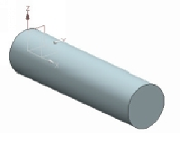
6.
Activate the
Extrude
command and select the right end face of the cylinder.
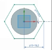
7.
Create a hexagon, as shown.
8.
Click
Finish
.
9.
Extrude the sketch up to 10 mm distance.
10.
On the ribbon, click
Tools > Utilities > Expression
.
11.
On the
Expressions
dialog, select
Listed Expressions > All
.
12.
Select
p7 (Extrude (1) Diameter Dimension on Arc1).
13.
Type
Diameter
in the
Name
box and click
Accept Edit
.
14.
Select
p18 (Extrude (2) Parallel Dimension between Line1 and Point2).
15.
Type
Diameter
in the
Formula
box and click
Accept Edit
.
16.
Select
p9 (Extrude (2) End Limit)
.
17.
Type
0.75*Diameter
in the
Formula
box and click
Accept Edit
.
18.
Click
OK
to update the model.