Biomedical Engineering Reference
In-Depth Information
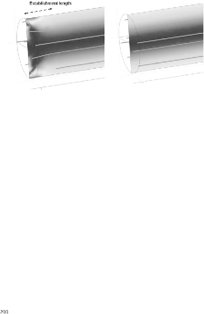
Figure 2.44
Vorticitycontourplotofanaxiallowinacylindricaltubeshowingtheestablishment
length.(a)Uniforminletvelocityand(b)inletvelocityieldgivenby(2.42).Thecontinuouslinesare
streamlines.
2.2.12 Distributing a Uniform Flow into a Microchamber
BioMEMS and immunoassays currently use microfluidic networks feeding the mi-
crochambers where the biological processes take place. Inside the capillary chan-
nels, the velocity profile is a Hagen-Poiseuille flow profile, parabolic for cylindrical
and rectangular channels, showing an important transverse gradient. For the pur-
poses of bioanalysis, labeled surfaces are installed inside the microchamber and it is
important that flow velocity should be as uniform as possible above all the labeled
surfaces. Labeled surfaces affected by a weak part of the main flow do not function
correctly.
A simple design of a divergent cone between the capillary channel and the mi-
crochamber cannot be satisfactory because it would result in a very nonuniform
velocity flow profile in the microchamber. We have used the COMSOL software
[48] to solve the incompressible Navier-Stokes equation. Figure 2.45 shows that
the velocity profile in a cross section of the microchamber is nearly parabolic. The
conditions for correct functioning of the device are then not met.
If the divergent cone is separated in subchannels as shown in Figure 2.46, the
velocity profile is very much improved, at least in the middle part of the cross sec-
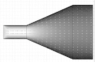
Figure 2.45
(a)Wideningfromamicroluidicchanneltoamicrochamber.(b)Nearlyparabolic
velocityproileinacrosssection,showingthatthemicrochamberwillnotbefedbyauniformluid
flow.