Biomedical Engineering Reference
In-Depth Information
Figure 2.46
(a)Wideningfromamicroluidicchanneltoamicrochamberusingsubchannels.(b)
Velocityproileinacrosssectionofthemicrochamber.TheproileisimprovedcomparedtoFigure
2.45.
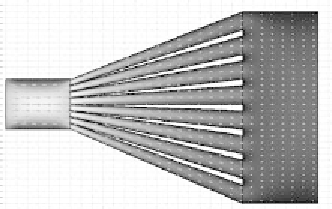
tion of the microchamber. Taking into account the requirements of lithography
techniques, we obtain the classical solution schematically represented in Figure
2.47. From left to right, each branch is divided into two subbranches, so that the
velocities are the same in all the branches of same size. The velocity profile is very
flat in the middle part of the microchamber cross section. This principle is applied
to design proteomic reactors (Figure 2.48), which will be described in the following
section.
We have shown here that by diverting the flow in many secondary flows, a
satisfactory widening can be achieved. However, the price to pay is an increased
friction, and the pressure drop is much higher in the solution of Figure 2.47 than
that of Figure 2.45.
2.2.13 The Example of a Protein Reactor
In a proteomic reactor, proteins are broken into peptides (or peptidic segments) by
the action of enzymes. The peptides are then separated according to their size inside
a chromatography column and finally expulsed into a mass spectrometer. The pro-
teins' composition is reconstructed after analysis of the identified peptides by the
reconstruction algorithms.
Figure 2.47
(a)Wideningfromamicroluidicchanneltoamicrochamberusinglithographytech-
nology.(b)Velocityproileinacrosssectionofthemicrochamber.