Biomedical Engineering Reference
In-Depth Information
2
ε ε
V
0
D
F
=
horizontal
2
d
(4.17)
2
ε ε
V
1
D
0
F
=
vertical
2
d
tan
θ
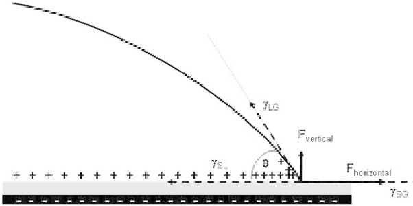
The SC mapping shows that the electric forces distribution on the liquid-gas inter-
face caused by the Maxwell-stress is limited to a very small region close to the triple
line. At a macroscopic scale, we can picture the situation as in Figure 4.7, and as-
sume that the forces are point forces acting on the triple line.
A balance of the forces—electric plus capillary—in the horizontal direction at
the triple line produces the BLY equation
2
ε
V
D
cos
θ
=
cos
θ
+
0
d
2
γ
LG
The electromechanical approach shows that the Lippmann term (electrowetting
number
h
) comes directly from the Maxwell stress on the liquid-gas interface. This
term can also be called electrostatic pressure. Another consequence of (4.17) is that
there is a vertical force on the liquid interface near the triple line. This vertical force
increases quickly when the contact angle decreases. This could be an explanation
for the phenomenon of the contact angle saturation that we present next. Remark
that, in reality, the interface angle with the wall is still the Young contact angle (Fig-
ure 4.8), the BLY contact angle being the global angle of the interface with the wall.
For large values of the applied voltage the interface profile is then very distorted.
4.2.2.3 Lippmann-Young Law and the Electrocapillary Equivalence
Another slightly different way of writing the Lippmann-Young law is
1
2
(4.18)
γ
cos
θ γ
-
cos
θ
=
CV
LG
LG
0
2
Figure 4.7
Resultant of the electric forces on the liquid-gas interface.