Biomedical Engineering Reference
In-Depth Information
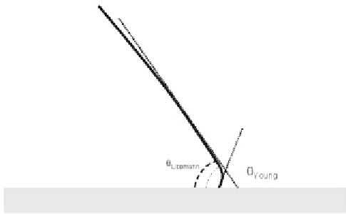
Figure 4.8
Real shape of the interface at the vicinity of the wall [12].
The first interpretation of the Lippmann-Young law stems from this equation:
when actuated, the contact angle of the droplet changes, resulting in an “apparent”
change of capillarity. It is very important here to note the word “apparent”; in
reality, the contact angle at the wall is not the Lippmann contact angle, but, at
some—not well defined—distance to the surface, the macroscopic contact angle
has the value defined by the BLY law. This explanation fails for dynamic motion, as
mentioned by Jones and coworkers. Indeed, the situation is quite different during
rapid dynamic motion of droplets under EWOD actuation; the contact angles are
not the equilibrium contact angles. This interpretation is not formally rigorous, but
it is very convenient in an engineering approach to explain many static or quasi-
static phenomena occurring in EWOD microsystems.
The second, more rigorous interpretation of the BLY law stems from (3.38).
In Chapter 3 we have seen that the capillary line force on a triple line with contact
angle
q
0
is given by
cap LG
f
(4.19)
This line force is directed in the solid plane perpendicularly to the triple contact
line and oriented outward. Following Jones et al. [7], Kang [8], and Zeng and Kors-
meyer [9], we have seen that the line tension electrostatic force is
=
γ
cos
θ
0
C
2
f
=
V
(4.20)
EWOD
2
The Lippmann-Young law—under the form (4.18)—can then be written as
f f f
(4.21)
Under such a form, the electrowetting effect is to add an electric force to the
capillary force on the triple line.
=
+
tot
cap
EWOD
4.2.2.4 Saturation—Modified BLY Law
Equation (4.1) predicts that a total wetting is obtained for a sufficiently high voltage.
This is not the case, and (4.1) breaks down above a certain voltage called the satura-