Information Technology Reference
In-Depth Information
scribes these signals.
Figure 17.7 shows two forward data transfer cycles. It has data followed by a command
phase. A high on the HostAck line indicates a data cycle, whereas a low indicates a com-
mand cycle. In the low state (command cycle) the data either represents an RLE count or a
channel address. The most significant bit of the data byte indicates whether it is an RLE
count or a channel address. If it is a 0, then bits the other 7 bits represent a RLE Count (from
0 to 127), else a 1 represents a channel address (from 0 to 127).
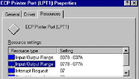
Figure 17.6
ECP input/output address ranges
Table 17.5
ECP mode signals
Compatibility
signal na
me
ECP mode name
In/out
Description
HostClk
I
Transfers data or address information in
the forward direction (along with Pe-
riphAck).
STROBE
HostAck
O
Command/Data status in the forward
direction. Data transfer in reverse direc-
tion (along with PeriphClk).
AUTO
FEED
1284Active
O
Set high when host is in a 1284 transfer
mode.
SELECT
INPUT
O
A low puts channnel in reverse direc-
tion.
INIT
ReverseReq
uest
PeriphClk
I
Transfer data in the reverse direction
(along with HostAck).
ACK
BUSY
PeriphAck
I
Transfer data or command information
(along with HostClk).
PE
nAckReverse
I
Acknowledgement to nReverseRequest.
SELECT
Xflag
I
Extensibility flag.
nPeriphRequest
I
Set low by peripheral to indicate that
reverse data is available.
ERROR
D0-D7
Data[8:1]
I/O
Data lines.